
Emergency or work related light bar

a technology for emergency or work-related light bars and bars, applied in vehicle headlamps, transportation and packaging, lighting and heating devices, etc., can solve the problems of no known light bars and many disadvantages

Active Publication Date: 2019-07-16
PUTCO
View PDF5 Cites 15 Cited by
  • Summary
  • Abstract
  • Description
  • Claims
  • Application Information

AI Technical Summary

Benefits of technology

This patent aims to improve upon existing technology by providing a light bar that can be used in a variety of applications and vehicles, including police cars, fire trucks, security vehicles, and ambulances. The light bar features LEDs of different colors and can be controlled remotely. It has a solid state design with more than two thousand chip-on-board LEDs and a compact size. Additionally, the light bar is flexible and can be installed on curved surfaces. The patent also offers light bars of different sizes that fit in the space between the bumper and the tailgate of most trucks, as well as in various window locations or externally on the vehicle.

Problems solved by technology

While conventional light bars provide many advantages, they suffer from many disadvantages not solved by the prior art.
No known light bars include the option to manually set a lighting pattern while simultaneously interpreting signals directly received from the electrical system of the vehicle.
Furthermore, there are no known light bars which reconcile whether a manual instruction from an operator of the vehicle or an automatic system for interpreting signals directly received from the electrical system of the vehicle should have priority over the other during simultaneous use.

Method used


Image

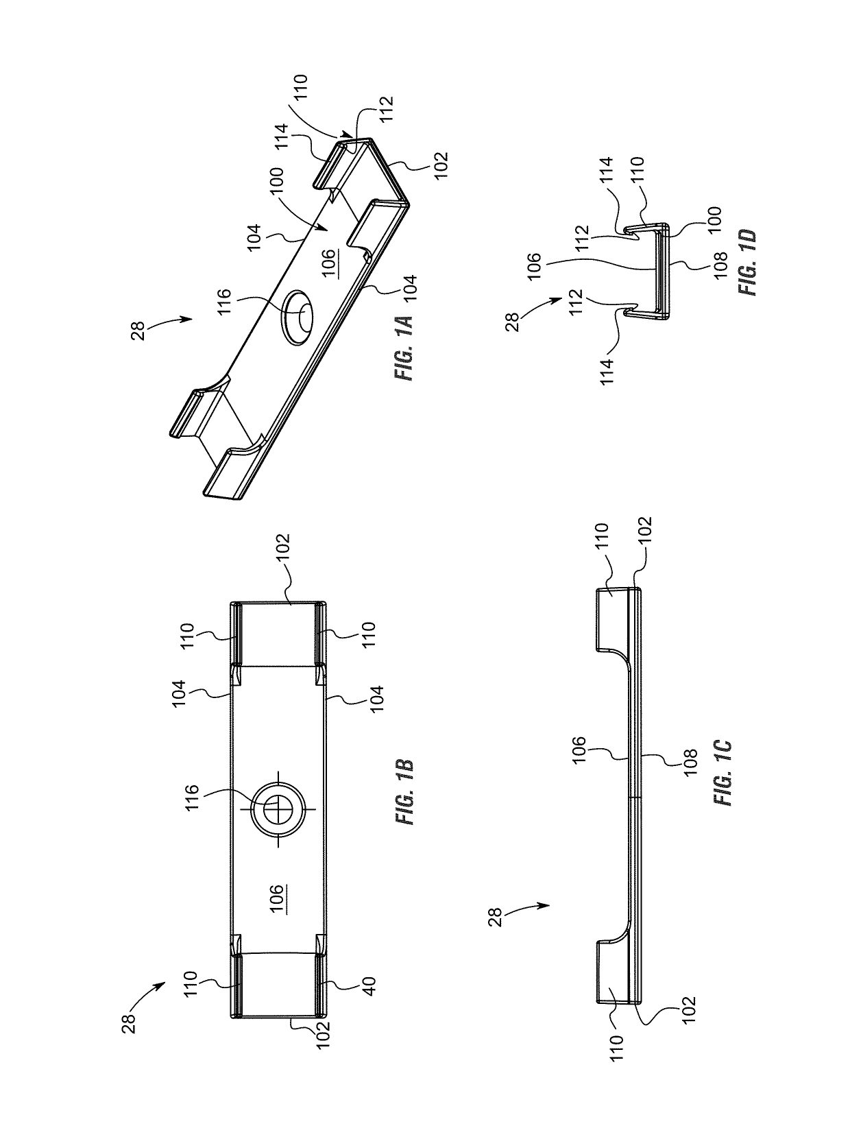
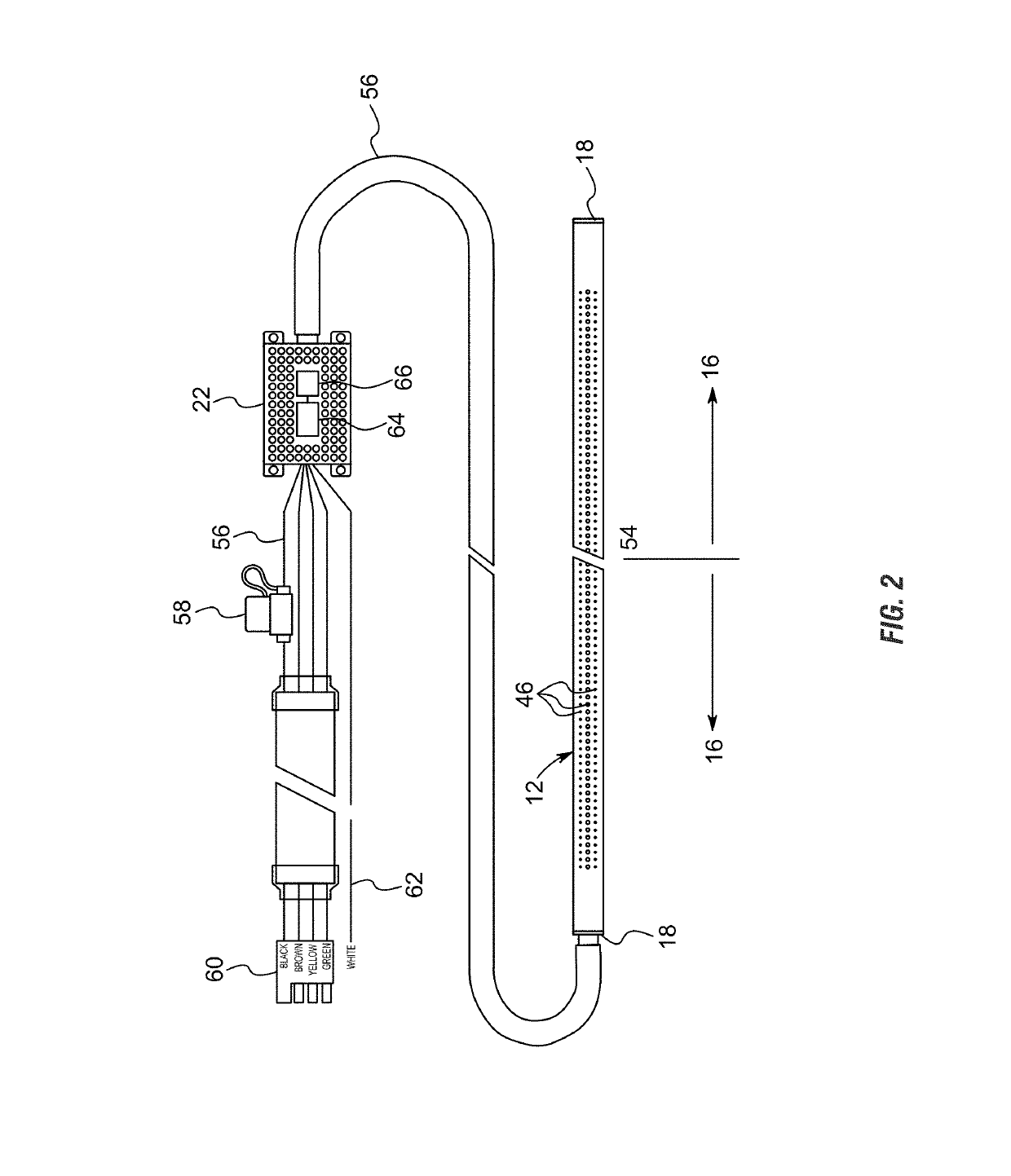
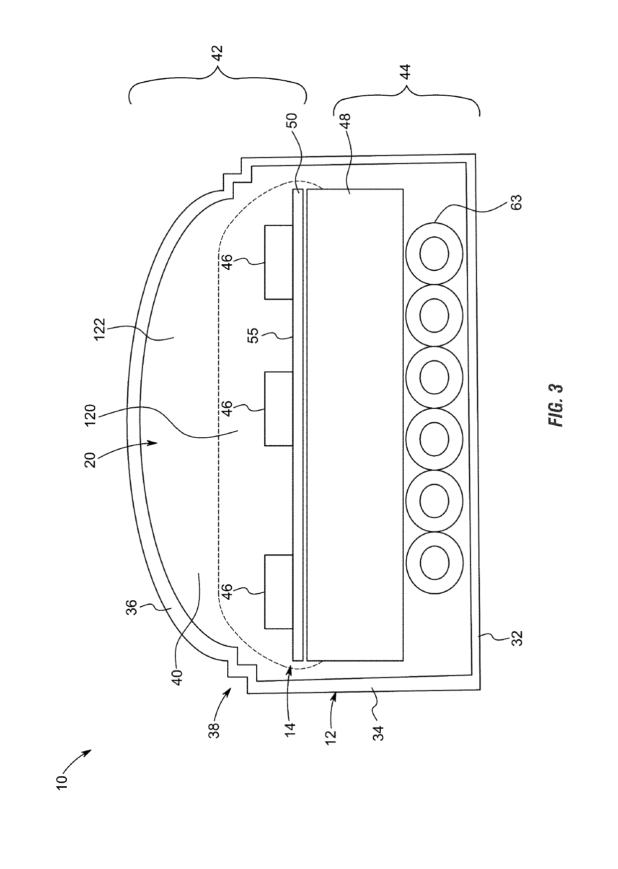
  • Emergency or work related light bar
  • Emergency or work related light bar
  • Emergency or work related light bar

Examples


Embodiment Construction

[0064]The following definitions and introductory matters are provided to facilitate an understanding of the present invention. Unless defined otherwise, all technical and scientific terms used herein have the same meaning as commonly understood by one of ordinary skill in the art to which embodiments of the present invention pertain.

[0065]The terms “a,”“an,” and “the” include plural referents unless context clearly indicates otherwise. Similarly, the word “or” is intended to include “and” unless context clearly indicate otherwise. The word “or” means any one member of a particular list and also includes any combination of members of that list.

[0066]The terms “invention” or “present invention” as used herein are not intended to refer to any single embodiment of the particular invention but encompass all possible embodiments as described in the specification and the claims.

[0067]The term “about” as used herein refers to variation in the numerical quantities that can occur, for example...


PUM


Abstract

A light bar has a circuit board positioned within a housing and having a plurality of light emitting diodes (LEDs) configured to transmit light from an outward facing surface of the circuit board. The housing has wiring electrically connected to a controller. The controller is configured to receive signals from the electrical system of the vehicle, interpret the signals received from the electrical system of the vehicle, and in response automatically control illumination of independently controllable segments of the vehicle light bar. An override mechanism within the controller allows an operator to manually override the automatic response to control illumination of the independently controllable segments with a selected strobing pattern. The override mechanism may be tied into the electrical system of the vehicle such that both the LEDs on the vehicle light bar and the external lights of the vehicle are synced.

Description

FIELD OF THE INVENTION[0001]This invention relates to lights. More specifically, and without limitation, this invention relates to a light bar which is particularly well suited for use on trucks in a low-profile manner in the space above a bumper and below the tailgate.BACKGROUND OF THE INVENTION[0002]The background description provided herein is for the purpose of generally presenting the context of the present disclosure. Work of the presently named inventors, to the extent the work is described in the present disclosure, as well as aspects of the description that may not otherwise qualify as prior art at the time of filing, are neither expressly nor impliedly admitted as prior art.[0003]Vehicle lights are old and well known. Countless forms of vehicle lights exist, including: headlights, fog lights, tail lights, reverse lights, parking lights, daytime running lights, and turning lights, among countless others. Each type of light or light configuration serves its own unique purpos...

Claims


Application Information

Patent Timeline
IPC IPC(8): F21S4/28B60Q1/22H05B33/08H01L27/15F21S41/141B60Q1/26H05B44/00
CPCB60Q1/22B60Q1/2696H05B33/083H01L27/153F21S41/141F21S43/14H01L25/0753B60Q1/0035B60Q1/2611B60Q1/2615H05B45/325H05B45/375B60Q2900/50H05B45/48
Inventor ELWELL, JAMES P.
Owner PUTCO
Learn More