
Device for filtering a plastic melt

a technology for filtration and plastic melts, applied in filtration separation, separation processes, chemistry apparatuses and processes, etc., can solve the problems of material, system size and cost, and achieve the effects of increasing mechanical stiffness of filter pins, increasing operational reliability, and convenient manufactur

Inactive Publication Date: 2019-07-16
MAAG AUTOMATIK GMBH
View PDF14 Cites 2 Cited by
  • Summary
  • Abstract
  • Description
  • Claims
  • Application Information

AI Technical Summary

Benefits of technology

[0007]According to the invention, a compact and easily maintainable device is thus provided, in which the functionalities of a filtering device and a start-up device are combined.
[0009]In one preferred embodiment, at least one web is formed in the filter pin in the region of the filter section of the filter pin, which web extends preferably in the axial direction through the filtrate cavity, wherein the drainage channel is designed to run within the at least one web. By forming the web, an increased mechanical stiffness of the filter pin can be achieved in this region, which can lead to a correspondingly increased operational reliability. In addition, if the drainage channel is designed to run through the web, a shortening of the necessary length of the filter pin in the axial direction can be achieved.
[0010]The at least one web may in particular have a cross-section in the shape of a polygon, preferably in the shape of a hexagon. This shape is suitable for a relatively easy manufacture of the at least one web and at the same time allows a favourable and relatively undisrupted flow behaviour of the plastic melt within the filtrate cavity. It also proves to be advantageous to arrange the filtering means between the at least one web and the at least one inlet channel. With particular preference, the polygon or the preferred hexagon has rounded edges in a manner favourable to the flow.
[0012]It is particularly preferred if, according to one preferred embodiment, the filter pin has next to the filter section a further pin section which corresponds in cross-section to the cross-section of the filter cavity in the housing, so that it fills this filter cavity in the filter change position. The feeding and discharging of plastic material to be filtered can thus be interrupted solely thereby in a manner that is simple in terms of design, for example when replacing the filtering means.

Problems solved by technology

It is therefore necessary to provide two different devices, which gives rise to an associated outlay in terms of material, system size and costs.

Method used


Image

  • Device for filtering a plastic melt
  • Device for filtering a plastic melt

Examples


Embodiment Construction

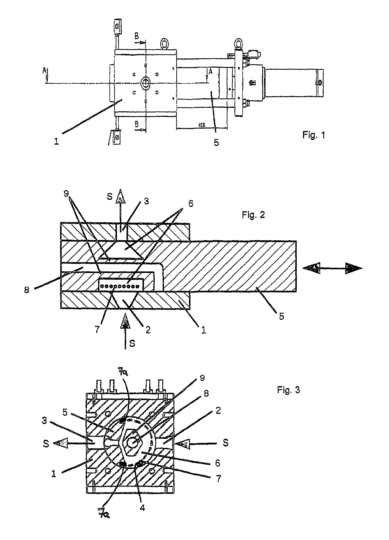
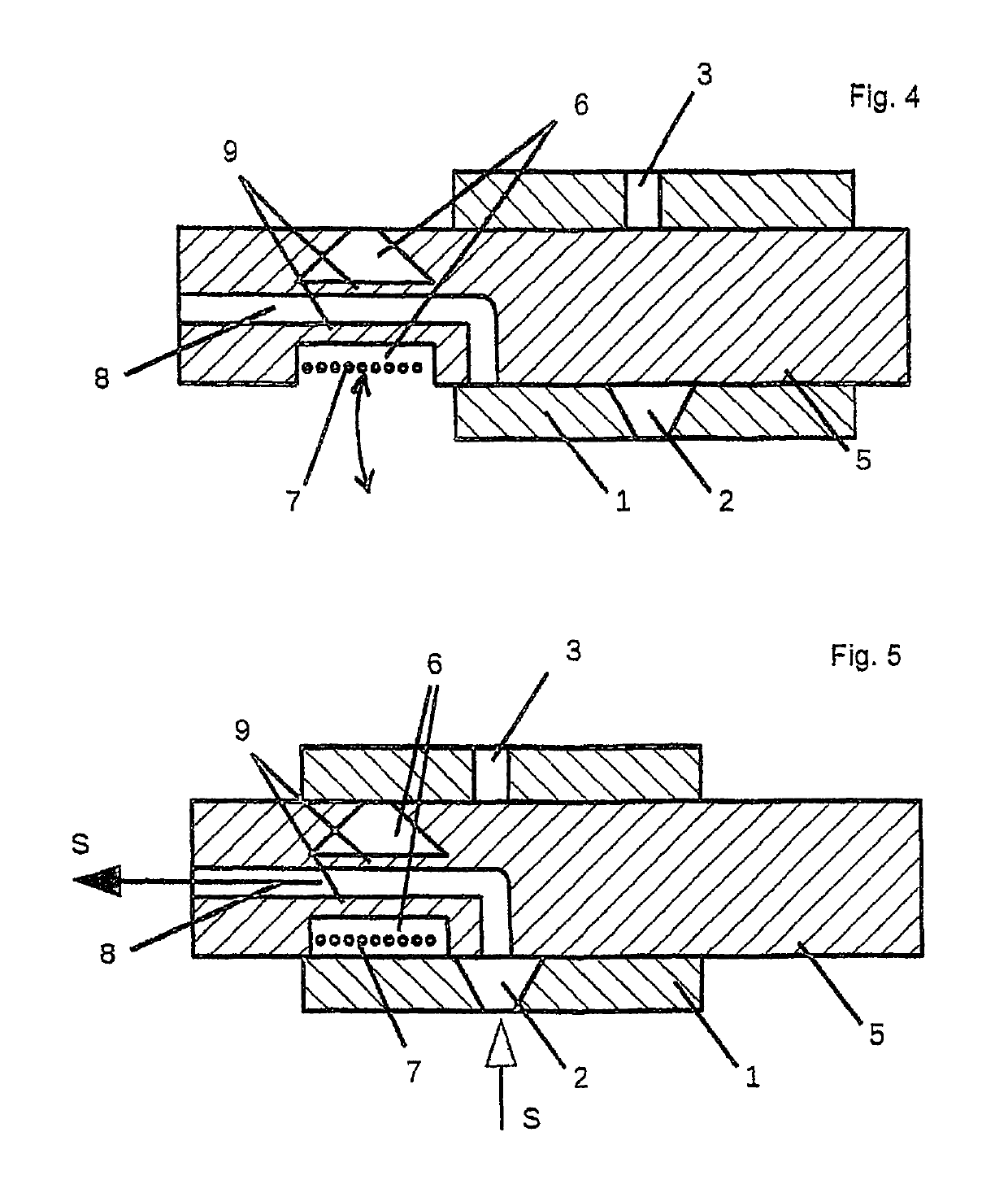
[0020]FIG. 1 schematically shows a device for filtering a plastic melt according to the invention. As shown in FIG. 2 and FIG. 3 as partial views in section along the line A-A and respectively the line B-B in FIG. 1, the housing 1 is provided with a cylindrical filter cavity 4, wherein the filter cavity 4 is provided with a filter pin 5 which is axially displaceable therein. The axial displaceability is indicated by the double-headed arrow in FIG. 2. In order to bring about the axial displacement of the filter pin 5, a hydraulic element is assigned to the pin.

[0021]FIGS. 2 and 3 show the filter pin 5 in a filtering position or working position. As seen in the flow direction of the plastic melt S that is to be filtered, said plastic melt passes via an inlet channel 2 into the housing 1, from there into the filter cavity 4 in the housing 1, is guided there through the filtering means 7, through which the plastic melt passes to a filtrate cavity 6. The filtrate cavity 6 is defined by t...


PUM

PropertyMeasurementUnit
angleaaaaaaaaaa
angleaaaaaaaaaa
angleaaaaaaaaaa

Abstract

A device for filtering a plastic melt, including a housing and a filter pin which is axially and / or radially movable therein. In a working position of the filter pin, plastic melt passes from an inlet channel, through a filtering mechanism, which is detachably fastened to the filter pin, to an outlet channel. In a filter change position of the filter pin, the filtering mechanism is freely accessible for replacing the filtering mechanism, and wherein at least one drainage channel is formed in the filter pin. In a start-up position of the filter pin, one end of the at least one drainage channel is in fluid connection with the at least one inlet channel in order to receive the plastic melt that is fed through the at least one inlet channel and to output the plastic melt at another end of the at least one drainage channel.

Description

FIELD OF THE INVENTION[0001]The invention relates to a device for filtering a plastic melt, in particular a thermoplastic melt. The device comprises a housing which has at least one inlet channel and at least one outlet channel for the plastic melt, wherein the at least one inlet channel is separated from the at least one outlet channel by at least one cavity for accommodating at least one filter pin which is axially and / or radially movable therein, wherein the at least one filter pin has a filter section to which at least one filtering means is detachably fastened so that the filter section of the at least one filter pin and the at least one filtering means define a filtrate cavity, wherein, in a working position of the filter pin, the plastic melt can pass from the at least one inlet channel through the filtering means to the filtrate cavity and the filtrate cavity is in fluid connection with the at least one outlet channel, and wherein, in a filter change position of the filter p...

Claims


Application Information

Patent Timeline
Patent Type & Authority Patents(United States)
IPC IPC(8): B01D29/96B29B15/00B29C48/27B01D29/00B29C48/69B29K101/12
CPCB01D29/96B01D29/0097B29C48/69B29K2101/12B29B15/00B29C48/2725
Inventor POHL, HARALDSTEINMANN, MARKUS
Owner MAAG AUTOMATIK GMBH
Learn More