
Method for controlling the liquid level in tanks as per characteristics of lamb waves and device for ultrasonic control of the liquid level in tanks

a technology of ultrasonic control and liquid level, which is applied in the direction of liquid/fluent solid measurement, engine lubrication, survey, etc., can solve the problems of reducing reliability and accuracy, affecting and instability of information signal in this method, so as to accelerate the process of calibration of a measuring scale and increase the accuracy of liquid level measurement. , the effect of increasing reliability

Inactive Publication Date: 2019-07-09
OBSCHESTVO S OGRANICHENNOI OTVETSTVENNOSTYU NAUCHNO ISSLEDOVATELSKY TSENTR TEKHNOAVTOMAT OOO NITS TEKHNOAVTOMAT
View PDF22 Cites 0 Cited by
  • Summary
  • Abstract
  • Description
  • Claims
  • Application Information

AI Technical Summary

Benefits of technology

[0021]The general task of the group of inventions and the required technical result achieved with the use of a group of inventions is to increase the accuracy (reliability) of controlling the level of liquid in the tank while increasing the speed of measurements (reducing the time for tuning up accurate measurements, in particular, by auto-calibrating the measuring scale) and expanding the field of application of the proposed group of inventions.
[0025]An essential difference between the proposed group of inventions is the use of the measurement of the energy characteristics (their ratios) of Lamb waves propagated between additional horizontal pairs of emitter / receiver for automatic calibration of the main measuring scale of the vertical pairs of emitter / receiver directly on site, thereby increasing the accuracy of liquid level measurements and simultaneously accelerating the process of calibration of a measuring scale, and also increasing reliability and expanding the scope, by covering those objects, also, where, for technological reasons, it is not possible to perform presetting of the device using trial draining or filling of liquids for initial calibration, with parallel use of other methods, direct or indirect ones, of controlling the liquid level at these facilities, so allowing to expand up to 100% the zone for controlling the liquid level in height for closed vessels (tanks) of an oval or round horizontal cross-section, as well as pipelines.

Problems solved by technology

The disadvantage of this method of controlling the liquid level, which reduces its reliability and accuracy, is the instability of the amplitude of the information signal when the thickness of the walls in the tank changes due to corrosion or exposure to aggressive media and overgrowing with residual components of the liquid reagents.
The instability of the information signal in this method is also caused by changes in the acoustic resistance of the contact layer between the acoustic transducers and the wall of the tank.
The disadvantage of this device is low reliability and accuracy caused by the dependence of information signals on the influence of destabilizing factors, for example, the changing acoustic resistance of the contact layer between the acoustic sensors and the tank wall.
A disadvantage of the second method for liquid level control is the insufficient reliability due to the fact that the paths and propagation velocities of the longitudinal wave and the Lamb wave are different, so the time interval for their reception can coincide (overlap) with the reception of reflected signals propagated in the tank wall.
Besides, the amplitude instability of its signal is due to the non-stable properties of the liquid, the level of which is controlled, for example, by the compressibility β, on which the speed of sound depends.
The disadvantages of this method of controlling the liquid level, which reduces its reliability and accuracy, include the fact that it uses a surface wave as a reference signal, velocity of which is less than the Lamb wave velocity, which is used as an information wave.
As a result, the time zone for receiving the reference signal can coincide with the action of other waves propagating in the wall of the tank, including reflected ones, which reduce the reliability of its signal identification.
The second disadvantage is related to the fact that the initial adjustment and start-up of the liquid level control a priori assumes the presence of a good acoustic contact between the emitter and the receiver, and also the relative invariance of the acoustic characteristics of the paths of the surface wave and the Lamb wave, which can not always be observed.
The disadvantages of this device are low reliability and complexity.
The design of the acoustic emitter and receiver, which comprises two piezoelectric transducers, thus forming two paths of signal conditioning by various elements of the acoustic emitter and receiver, requires the identical influence of external factors, in particular, temperature, on the characteristics of these elements, which is practically difficult and leads to distortion of the final signal informing about the position of the monitored liquid level.
Insufficient accuracy is also due to the fact that the hysteresis characteristic of the amplitude of the information signal as a function of the position of the liquid level in the control zone closely adjacent to the line on which the acoustic emitter and receiver are located creates an ambiguous relationship between the set point of the amplitude of the information signal and the position of the liquid level in this zone.
Insufficient reliability of the device is due to its complexity.
Actually, additional complicated technical procedures are required to meet this condition.
Moreover, this patent considers only cases of either vertical or horizontal arrangement of pairs of transducers and measurements are made only on these individual pairs, and the results of measurements obtained from horizontal pairs are not used to increase the accuracy of measurements obtained from vertical pairs by adjusting (graduating) the measuring scale.
However, the use of an anti-symmetric Lamb wave only (and a symmetric one only, too) is affected by destabilizing factors (for example, temperature, etc.) in the process of measurement, which inevitably makes measurements less accurate.
The disadvantage of this method is the need for preliminary calibration of at least the initial and final values of the measuring scale, which presupposes the fixation of these values with a deliberately filled and drained tank to levels beyond the control zone (above and below the sensor installation area), and knowing and taking into account the parameters of the tank wall, which affect the characteristics of the Lamb wave, which, in general, is not always possible.
Without the use of additional level control means that allow the calibration scale to be calibrated directly on site, it is not possible to achieve accurate measurements, as well as high speed of their conduct.
Prior to putting the device into operation, this calibration procedure requires at least one full cycle of draining or filling the tank with liquid in such a way that the liquid level passes through the entire established control zone with the fixation of the required level control points by other means, which is not always possible.
For example, in the case of an oil tank with a capacity of several thousand tons, a test drain or fill, even a small level for adjusting the scale, will be impossible for technological reasons due to large volumes of pumping, which can be available only under operating conditions.
The above drawbacks limit the scope of the device and do not provide accurate measurements within a short period of time (i.e., to perform high-speed fine-tuning to get precise measurements).

Method used


Image

  • Method for controlling the liquid level in tanks as per characteristics of lamb waves and device for ultrasonic control of the liquid level in tanks
  • Method for controlling the liquid level in tanks as per characteristics of lamb waves and device for ultrasonic control of the liquid level in tanks
  • Method for controlling the liquid level in tanks as per characteristics of lamb waves and device for ultrasonic control of the liquid level in tanks

Examples


Embodiment Construction

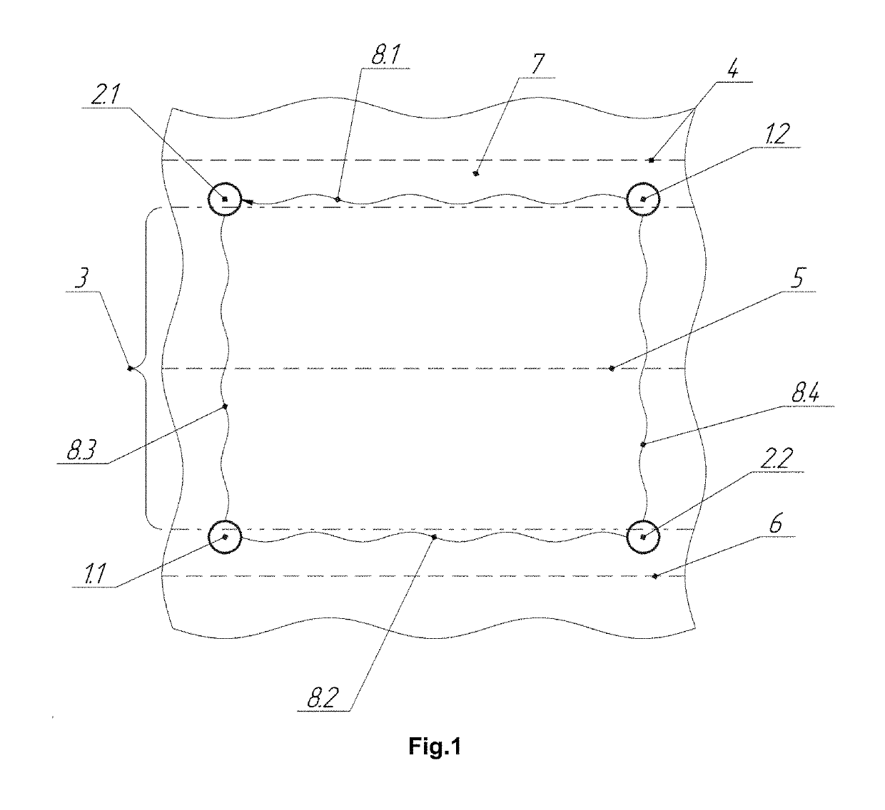
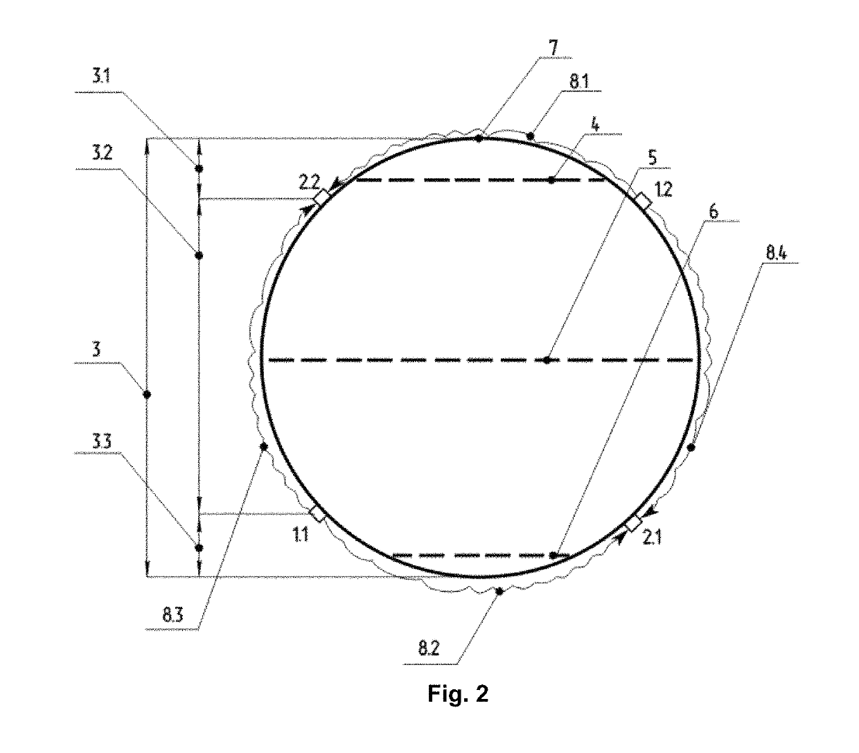
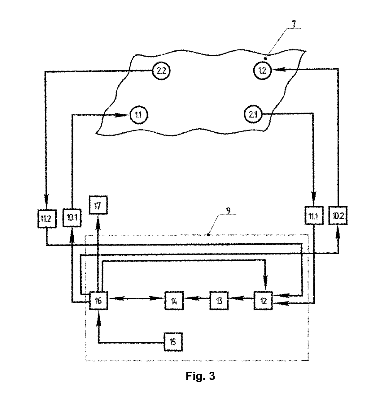
[0030]The device for control the liquid level in the tanks comprises (FIG. 3) the first acoustic emitter 1.1 and the first acoustic receiver 2.1 fixed to the outer surface 7 of the tank (reservoir), forming the first horizontally arranged pair of acoustic transducers, and the second acoustic emitter 1.2 and the second acoustic receiver 2.2, forming the second horizontally arranged pair of acoustic transducers, each comprising one piezoelectric transducer (not shown in the diagram). In this case, the first and second pairs of acoustic transducers are installed along different lines parallel to each other and liquid level simultaneously, at fixed distances, both horizontally and vertically, forming the first vertically arranged pair consisting of the first acoustic emitter 1.1 and the second acoustic receiver 2.2 and the second vertically arranged pair consisting of the second acoustic transmitter 1.2 and the first acoustic receiver 2.1. The distance between the horizontal pairs of ac...


PUM


Abstract

The present method makes use of a second receiver-transmitter pair, which, together with a first pair, forms a quadrilateral figure, the horizontal sides of which are parallel to the level of a liquid. In addition, the values of the energy characteristics of Lamb waves propagated simultaneously both between each of the horizontal receiver-transmitter pairs and between a second vertical receiver-transmitter pair are calculated using values obtained from certain horizontal pairs to determine the initial and final values of the measuring scale of other pairs, by means of which the height of the liquid level is determined and / or measured. The device comprises an acoustic receiver and an emitter, each provided with a piezoelectric transducer, which are mounted at a set distance from one another such that a liquid level monitoring region lies therebetween for the simultaneous excitation of a symmetrical and an antisymmetric normal zero mode Lame wave, the device further comprising a second acoustic receiver-transmitter pair and a signal generating and converting unit. Technical result: increased monitoring accuracy together with increased monitoring speed and a broader scope of application.

Description

[0001]This application is the U.S. national phase of International Application No. PCT / RU2016 / 000470 filed Jul. 22, 2016 which designated the U.S. and claims priority to Russian Application No. 2015131984 filed Jul. 31, 2015, the entire contents of each of which are hereby incorporated by reference.FIELD OF THE INVENTION[0002]The proposed group of inventions refers to the technology of controlling the technological parameters of liquid media in tanks for industrial production and can find application in the chemical, oil and gas, food and other industries.BACKGROUND OF THE INVENTION[0003]A method for ultrasonic control of the level of liquid in tanks is known (USSR certificate of authorship No. 343155, G 01 F 23 / 28, 1972), in which a longitudinal ultrasonic wave is introduced into the tank wall at an angle to it and parallel to the surface of the monitored medium; the velocity of the trace of this wave on the input surface is set equal to the velocity of a normal wave (Lamb wave) pr...

Claims


Application Information

Patent Timeline
Patent Type & Authority Patents(United States)
IPC IPC(8): E21B47/16G01F25/00G01F23/296
CPCG01F25/0061G01F23/2965G01F25/20G01F23/296
Inventor TOKAREV, VYACHESLAV GRIGOREVICHKACHANOV, OLEG MIHAYLOVICHKURENKOV, ANTON IVANOVICHROMANOV, ANDREI VLADIMIROVICHARISTOV, DMITRY VIKTOROVICH
Owner OBSCHESTVO S OGRANICHENNOI OTVETSTVENNOSTYU NAUCHNO ISSLEDOVATELSKY TSENTR TEKHNOAVTOMAT OOO NITS TEKHNOAVTOMAT
Learn More