
Retractable pen

a pen and pen handle technology, applied in the field of pen, can solve problems such as the formation of undesired handwriting strokes, and achieve the effect of reducing the probability of making handwriting errors

Active Publication Date: 2019-07-09
WU CHIEN MING
View PDF4 Cites 3 Cited by
  • Summary
  • Abstract
  • Description
  • Claims
  • Application Information

AI Technical Summary

Benefits of technology

[0005]A primary object of the present invention is to provide a retractable pen, which includes an ink cartridge having a tip that, when being moved to an extended position for writing, is continuously pressed against a lead-out opening of the pen without the risk of swaying during the whole course of writing.
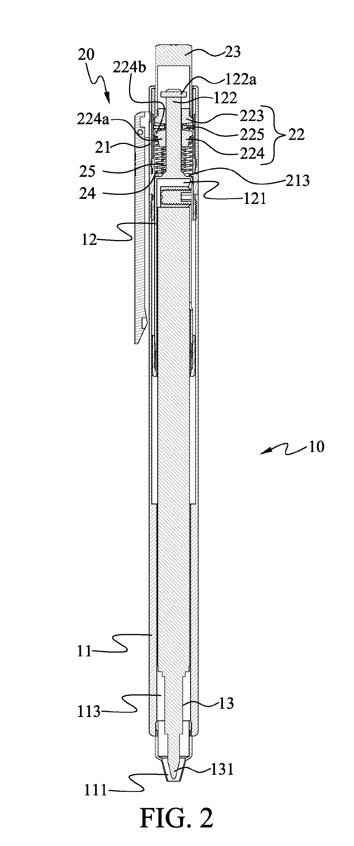
[0007]The switching device is mounted between the barrel and the ink cartridge for causing the tip to move between an extended position, in which the tip is projected from the lead-out opening of the barrel, and a retracted position, in which the tip is located in the barrel. Since the lead-out opening of the barrel has an inner diameter smaller than the outer diameter of the tip, the tip moved to the extended position is pressed against and immovably held to the lead-out opening.
[0009]The resetting member can elastically bring the tip from the extended position to the retracted position. The deformable member is mounted between the shifting member and the ink cartridge. When the tip is located at the extended position and the shifting member is located at a third position within the shifting path before being moved to the second position, the deformable member can be compressed and deformed by between the shifting member and the ink cartridge, allowing the shifting member to be further moved from the third position to the second position
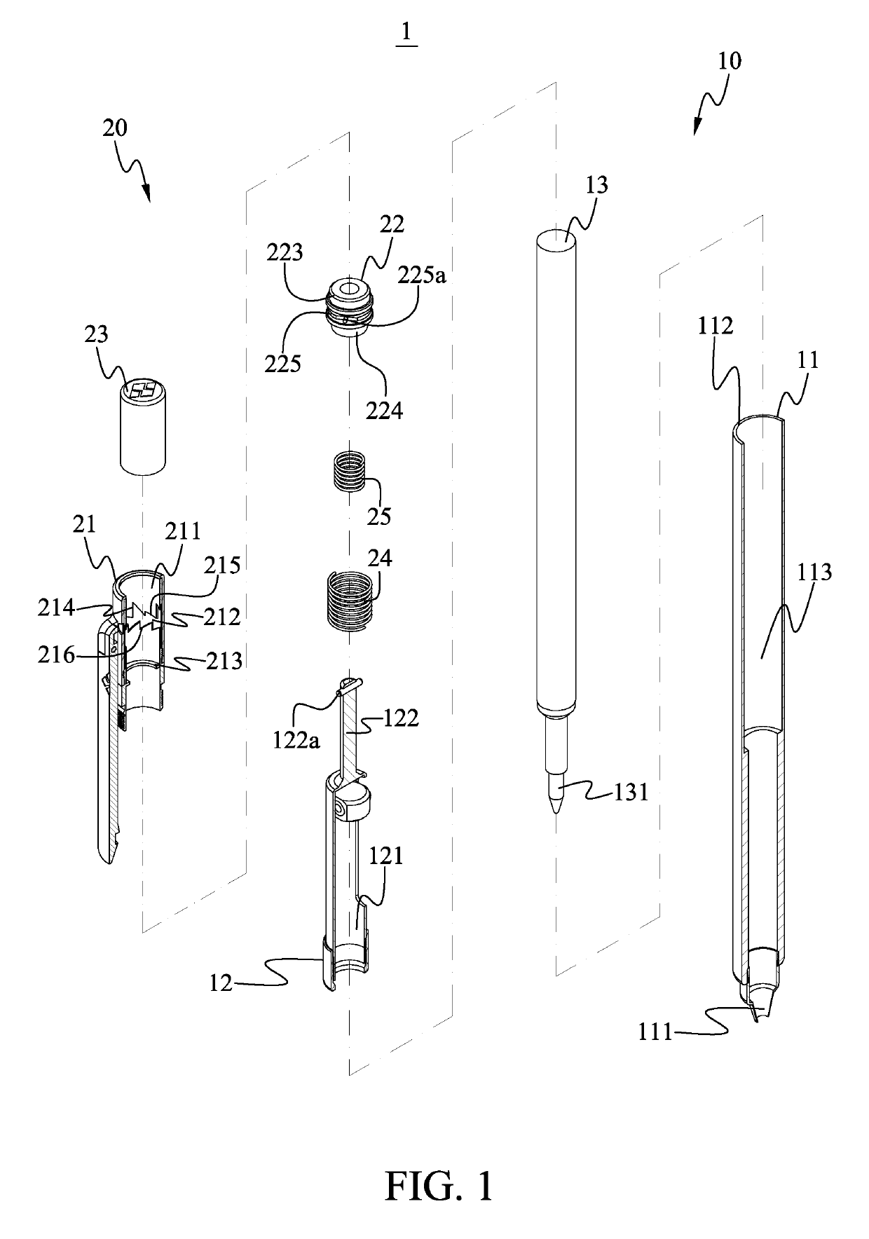
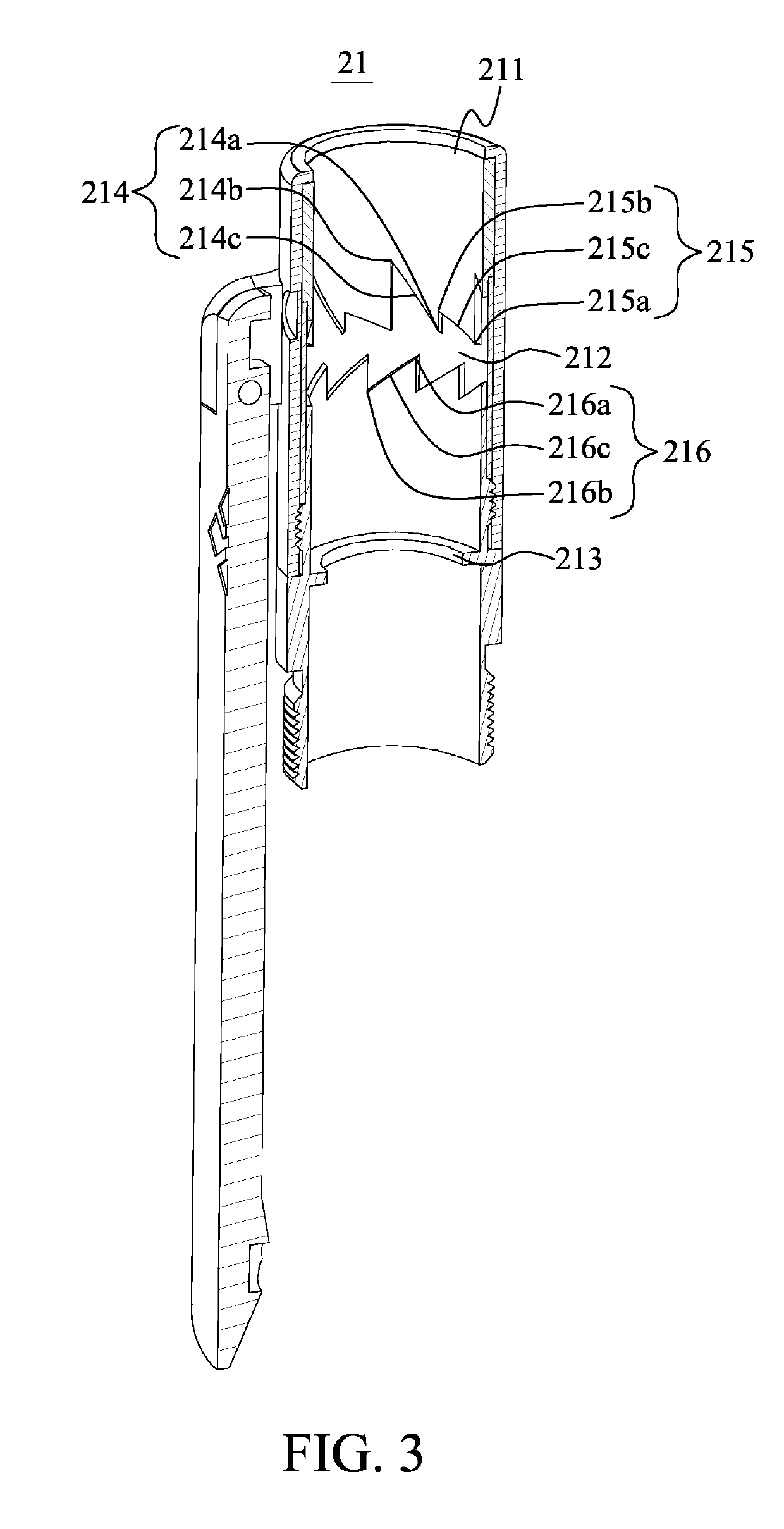
[0014]The shifting member includes a lower slide block, an upper slide block and a shifting plate located between the lower and the upper slide block, such that the lower slide block and the shifting plate are brought by the upper slide block to move. The lower slide block includes a first body portion and a second body portion formed on a top of the first body portion; and the deformable member has an end pressing against the first body portion. The limiting member is internally formed with a radially inward extended abutting seat; and the resetting member has an end pressing against the abutting seat and another end pressing against the second body portion of the shifting member. When the tip is moved from the retracted position to the extended position, the resetting member is compressed by between the abutting seat and the second body portion to have a shortened length.
[0023]The present invention is characterized in that the tip located at the extended position is pressed against and held to the lead-out opening of the barrel, and that the deformable member compressed and deformed by between the ink cartridge and the shifting member allows the shifting member to be moved from the third position to the second position when the tip has been held to the lead-out opening and can not be moved any further. When the shifting member is located at the second position, the locating block thereof is pressed against the second stop point and the tip is continuously pressed against and held to the lead-out opening of the barrel without the risk of swaying when a user writes with the retractable pen. With these arrangements, the probability of making errors in handwriting can be reduced.

Problems solved by technology

The inclined tip would possibly cause the forming of undesired handwriting strokes when using the click ball pen to write.

Method used


Image

  • Retractable pen
  • Retractable pen
  • Retractable pen

Examples


Embodiment Construction

[0040]The present invention will now be described with some preferred embodiments thereof and by referring to the accompanying drawings. For the purpose of easy to understand, elements that are the same in the preferred embodiments are denoted by the same reference numerals.

[0041]Please refer to FIGS. 1 and 2. A retractable pen 1 according to a first preferred embodiment of the present invention includes a body 10 and a switching device 20. The body 10 includes a cylindrical barrel 11, which has a lower end forming a forward tapered lead-out opening 111 and an upper end forming a round lead-in opening 112 and internally defines a receiving space 113 between the lead-out opening 111 and the lead-in opening 112. In the receiving space 113, there are mounted a clamping member 12 and an ink cartridge 13. The clamping member 12 has a lower part internally defining an assembling space 121 and an upper part forming an assembling stem 122, which is upward projected from the lead-in opening ...


PUM


Abstract

A retractable pen includes a barrel, an ink cartridge, a limiting member, a shifting member and a deformable member. When the shifting member is moved relative to the limiting member between a first position and a third position, the ink cartridge can be moved from a retracted position to an extended position or from the extended position to the retracted position. When the ink cartridge is located at the extended position, the deformable member can be further compressed by between the shifting member and the ink cartridge, allowing the shifting member to be moved further from the third position to a second position closer to the ink cartridge. When the shifting member is located at the second position, the ink cartridge is continuously held to the extended position and pressed against a lead-out opening of the barrel without the risk of swaying when a user writes with the retractable pen.

Description

FIELD OF THE INVENTION[0001]The present invention relates to a pen, and more particularly to a retractable pen including an ink cartridge having a tip that, when being moved to an extended position for writing, is continuously pressed against a lead-out opening of the pen without the risk of swaying during the whole course of writing.BACKGROUND OF THE INVENTION[0002]A ball pen is a writing instrument. Ink filled in an ink cartridge received in a barrel of the ball pen flows to a metal ball at a tip of the pen under the action of atmospheric pressure and gravity of ink. The metal ball rotates when the ball pen is used to write on paper, and ink is transferred from the rotating metal ball to the paper to form handwriting strokes. Currently, click ball pens are very common in the market. By clicking downward on the top of the ball pen, the tip of the ink cartridge is extended from a bottom opening of the barrel or retracted into the barrel.[0003]To allow the tip of the ink cartridge to...

Claims


Application Information

Patent Timeline
Patent Type & Authority Patents(United States)
IPC IPC(8): B43K24/08B43K7/12
CPCB43K7/12B43K24/084B43K24/08
Inventor WU, CHIEN MING
Owner WU CHIEN MING
Learn More