Passive heat removal system for nuclear power plant

a technology of passive residual heat removal and nuclear power plants, which is applied in the direction of nuclear reactors, greenhouse gas reduction, nuclear elements, etc., can solve the problems of difficult to achieve the target performance of the passive residual heat removal system, the flow of the passive residual heat removal system is affected during an accident, and the performance of the passive residual heat removal system is generally known to be big. , to achieve the optimal performance of the passive residual heat removal system, the effect of preventing the performance degradation of a condensation

Active Publication Date: 2019-06-18
KOREA ATOMIC ENERGY RES INST
View PDF16 Cites 1 Cited by
  • Summary
  • Abstract
  • Description
  • Claims
  • Application Information

AI Technical Summary

Benefits of technology

[0014]An object of the present disclosure is to prevent the dysfunction of a makeup tank associated with a flow at a secondary side of a passive residual heat removal system and alleviate the performance degradation and prediction uncertainty of a condensation heat exchanger due to non-condensable gas to overcome the foregoing problems in the related art.

Problems solved by technology

However, the passive residual heat removal system is generally known to exhibit a big difference in the cooling performance according to a coolant flow of the secondary side including the steam generator.
Furthermore, a flow of the passive residual heat removal system during an accident is affected by a time point at which the discharge of steam is suspended or the supply of feedwater is suspended by related signals (valve closed or pump stopped) during the accident.
As described above, a coolant flow at a secondary side including the steam generator is affected by an initial water level of the steam generator and a time point at which steam discharge or feedwater is stopped, and the like, and if the coolant flow is unable to maintain an appropriate flow level, it is difficult to accomplish the target performance of the passive residual heat removal system.
However, a conventional makeup tank is configured to supply a flow even when the flow is sufficient in a system, thus rather acting as a cause of deteriorating the performance of the passive residual heat removal system.
However, the patent does not disclose a specific pressure drop scheme, and a connection line is provided subsequent to the main steam isolation valve, and as a result, if the isolation valve of the exhaust line is not closed when the passive residual heat removal system is operated during an accident, then there is a possibility in which the coolant of the passive residual heat removal system is lost through the exhaust line to cause a serious accident.
As a result, when an accident requiring the operation of the passive residual heat removal system occurs, the accumulated non-condensable gas may flow into the condensation heat exchanger to prevent steam condensation to cause the performance degradation of the condensation heat exchanger.
However, as a high pressure (for example, SMART reactor: 17 MPa) facility, the passive residual heat removal system has a problem of significantly increasing the cost due to an increase of capacity.
Furthermore, as a high-temperature high-pressure facility, the reactor restricts rapid cooling to alleviate thermal shock other than a normal operation and a partially restrictive accident.
Accordingly, there is a limit in designing that the capacity of the condensation heat exchanger is conservatively too large.

Method used


Image

  • Passive heat removal system for nuclear power plant
  • Passive heat removal system for nuclear power plant
  • Passive heat removal system for nuclear power plant

Examples


Embodiment Construction

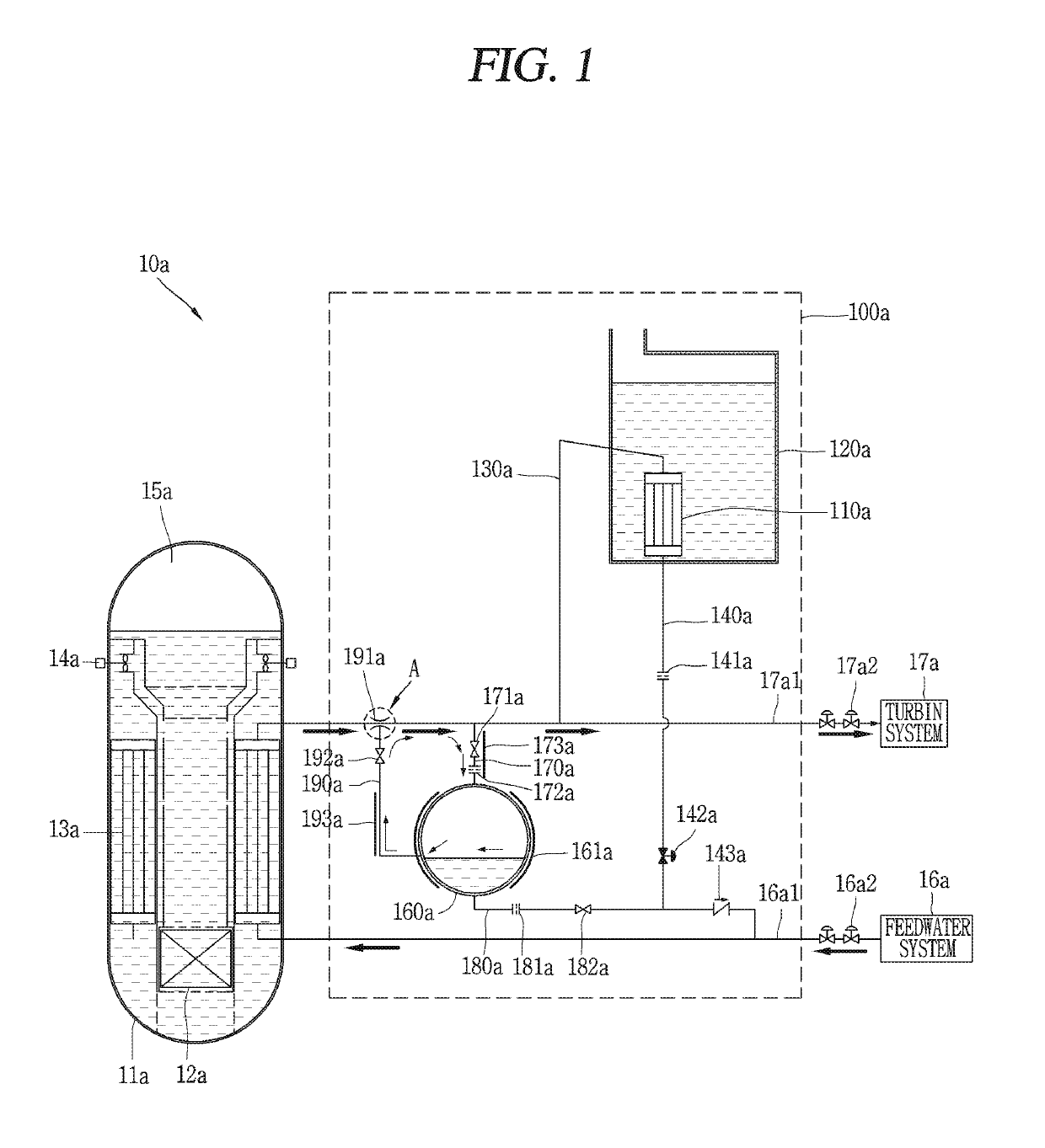
[0060]Hereinafter, a nuclear power plant including a passive residual heat removal system associated with the present disclosure will be described in more detail with reference to the accompanying drawings. Even in different embodiments according to the present disclosure, the same or similar reference numerals are designated to the same or similar configurations, and the description thereof will be substituted by the earlier description. Unless clearly used otherwise, expressions in the singular number used in the present disclosure may include a plural meaning.

[0061]In the specification, in case where it is mentioned that an element is “connected” to another element, it should be understood that an element may be directly connected to another element, but another element may exist therebetween. On the contrary, in case where it is mentioned that an element is “directly connected” to another element, it should be understood that any other element does not exist therebetween. It is ...


PUM


Abstract

The present invention relates to a passive heat removal system which circulates cooling fluid to a steam generator via a main water supply line connected to the lower inlet of the steam generator, and a main steam pipe connected to the top outlet of the steam generator, to remove sensible heat of a nuclear reactor coolant system and residual heat of a core. The heat removal system comprises supplementary equipment for receiving surplus cooling fluid or for supplying supplementary cooling fluid in order to maintain the flow rate of the cooling fluid within a predetermined range. The supplementary equipment comprises: a supplementary tank, installed at a height between the lower inlet and the top outlet of the steam generator; a first connection pipe, connected to the main steam pipe and the supplementary tank; and a second connection pipe, connected to the supplementary tank and the main water supply pipe.

Description

CROSS-REFERENCE TO RELATED APPLICATIONS[0001]This application is the National Stage filing under 35 U.S.C. 371 of International Application No. PCT / KR2015 / 007635, filed on Jul. 22, 2015, which claims the benefit of earlier filing date and right of priority to Korean Application No. 10-2014-0093457, filed on Jul. 23, 2014, the contents of which are all hereby incorporated by reference herein in their entirety.BACKGROUND OF THE INVENTION[0002]1. Field of the Invention[0003]The present disclosure relates to a passive residual heat removal system used as one of emergency safety facilities and a nuclear power plant including the same.[0004]2. Description of the Related Art[0005]A residual heat removal system is an emergency safety facility for removing sensible heat in a reactor coolant system and residual heat in a reactor core during an accident. In particular, the passive residual heat removal system removes sensible heat and residual heat in a passive manner using natural forces.[000...

Claims


Application Information

Patent Timeline
Patent Type & Authority Patents(United States)
IPC IPC(8): G21C15/18G21C1/32
CPCG21C15/18G21C1/326Y02E30/40Y02E30/30G21C9/012
Inventor KIM, YOUNG INKIM, KEUNG KOOYOON, JU HYEONHA, JAE JOOKIM, TAE WANPARK, CHEON TAERYU, SEUNG YEOBKANG, HAN OKBAE, YOUNG MINMOON, JOO HYUNGHAN, HUN SIKKANG, KYUNG JUNSHIN, SOO JAIJUNG, SEO YOONKIM, YOUNG SOO
Owner KOREA ATOMIC ENERGY RES INST
Why Eureka
Try Eureka