Undulator magnet array and undulator
a technology of undulator magnet array and undulator, which is applied in the direction of magnets, magnetic bodies, nuclear engineering, etc., can solve the problem of insufficient intensity of magnetic fields, and achieve the effect of reducing magnetic forces
- Summary
- Abstract
- Description
- Claims
- Application Information
AI Technical Summary
Benefits of technology
Problems solved by technology
Method used
Image

Examples
first embodiment
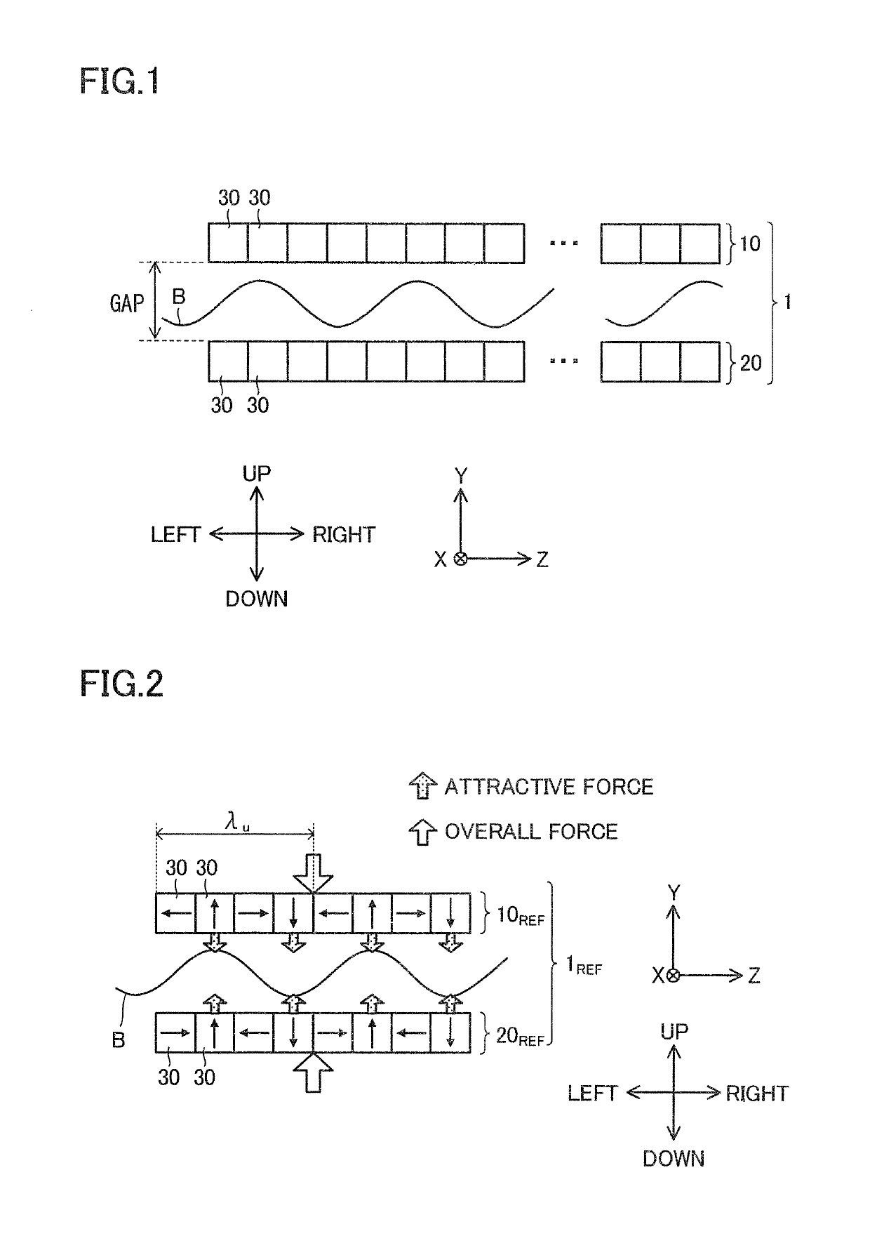
[0036]A first embodiment of the present invention will be described. FIG. 1 shows the structure of an undulator magnet array 1 according to the first embodiment. The undulator magnet array 1 has two magnet arrays 10 and 20 disposed parallel to each other with an interval in between so as to lie opposite each other. The magnet arrays 10 and 20 are each composed of a plurality of magnets 30 arranged in a straight line. The magnets 30 are permanent magnets such as neodymium magnets. Unless otherwise stated, the magnets 30 that constitute the magnet arrays 10 and 20 all have the same shape and the same size, and in each magnet array, the plurality of magnets 30 are arranged at a constant pitch.
[0037]In this embodiment, for the sake of concrete explanation, three mutually perpendicular axes are assumed, namely X-axis, Y-axis, and Z-axis. Z-axis is parallel to the arrangement direction of the magnets 30 in each magnet array. The arrangement direction of the magnets 30 is the same between ...
second embodiment
[0087]A second embodiment of the present invention will be described. The second embodiment, as well as the third to fifth embodiments described later, is based on the first embodiment, and to the features of the second to fifth embodiments that go unmentioned in the following description, the description of the corresponding features in the first embodiment applies unless inconsistent. Features from different ones of the first to fifth embodiments may be combined together unless inconsistent.
[0088]The amount of leftward shift Δz (example of predetermined shift amount) of the upper shifted magnet array relative to the lower reference magnet array will be defined in terms of the phase φz. The amount of leftward shift of the lower shifted magnet array relative to the upper reference magnet array also equals Δz. The phase φz corresponding to one period λu equals 2π in radian notation. Therefore, the phase φz is given by “φz=2π×Δz / λu”. In the undulator magnet array 1REF, no shifting as ...
third embodiment
[0100]A third embodiment of the present invention will be described. Although the first embodiment assumes that the number M of magnets 30 present in one period λu is four, it is also possible to form an undulator magnet array 1 where M is other than four. As examples, undulator magnet arrays 1 where M=2 or M=8 will be described below, with no intention of excluding undulator magnet arrays 1 where M is other than 2, 4, and 8.
[0101]FIG. 15 is a diagram showing the configuration of an undulator magnet array 1PA formed with M=8. The undulator magnet array 1PA is an example of the undulator magnet array 1, and includes an upper magnet array 10PA and a lower magnet array 20PA as an example of the upper and lower magnet arrays 10 and 20 respectively. The upper magnet array 10PA is formed by coupling together one upper shifted magnet array 10SPA and one upper reference magnet array 10RPA. The lower magnet array 20PA is formed by coupling together one lower reference magnet array 20RPA, whi...
PUM
| Property | Measurement | Unit |
|---|---|---|
| weight | aaaaa | aaaaa |
| angle | aaaaa | aaaaa |
| angle | aaaaa | aaaaa |
Abstract
Description
Claims
Application Information
 - R&D
- Intellectual Property
- Life Sciences
- Materials
- Tech Scout
- Unparalleled Data Quality
- Higher Quality Content
- 60% Fewer Hallucinations
Browse by: Latest US Patents, China's latest patents, Technical Efficacy Thesaurus, Application Domain, Technology Topic, Popular Technical Reports.
© 2025 PatSnap. All rights reserved.Legal|Privacy policy|Modern Slavery Act Transparency Statement|Sitemap|About US| Contact US: help@patsnap.com