
Coupled recognition/detection system for in vivo and in vitro use

a recognition/detection system and in vitro technology, applied in the field of in vitro and in vitro use of coupled recognition/detection systems, can solve the problems of limited rna visualization technology, inability to achieve homogeneous assays, and inability to use similar simple and straightforward technologies for rna and small molecule visualization, etc., to achieve rapid, simple and general approach, and improve the number of molecules

Active Publication Date: 2019-06-11
CORNELL UNIVERSITY
View PDF10 Cites 1 Cited by
  • Summary
  • Abstract
  • Description
  • Claims
  • Application Information

AI Technical Summary

Benefits of technology

[0049]A twenty-second aspect of the invention relates to a method of monitoring a target molecule in a cell that includes: introducing into a cell a gene encoding the nucleic acid molecule according to the fourth aspect of the invention (where the first domain binds to the fluorophore only after the second domain binds to the target molecule), wherein the second domain binds the target molecule; introducing into the cell a first fluorophore having a methyne bridge between a substituted aromatic ring system and a substituted imidazol(thi)one, oxazol(thi)one, pyrrolin(thi)one, or furan(thi)one ring, wherein the first fluorophore is bound specifically by the first domain of the nucleic acid molecule to enhance fluorescence emissions by the first fluorophore; exposing the cell to radiation of a wavelength suitable to induce fluorescence emissions by the first fluorophore that is bound by the nucleic acid molecule or a FRET partner; and measuring the fluorescent emissions of the first fluorophore or the FRET partner to monitor the target molecule. This aspect is particularly useful for monitoring the location, degradation (over time), and for quantitating the target molecule (i.e., based on the level of fluorescence). Moreover, simultaneous monitoring of two or more target molecules is possible.
[0055]The examples of the present invention demonstrate the development of an array of fluorophores that exhibit low fluorescence in the absence of specific binding by a nucleic acid aptamer molecule, resulting in an aptamer / fluorophore complex that contains a fluorophore whose fluorescence can be “switched on” only when bound specifically by the aptamer. This solves the problem of many prior art fluorophores, which contribute indiscriminately to background fluorescence. The aptamer / fluorophore complexes of the invention are useful for a wide variety of purposes, both in vitro and in vivo, including monitoring the location or degradation of RNA molecules in vivo, monitoring and quantifying the amount of a target molecule in an in vitro or in vivo system. Importantly, the fluorophores are non-toxic, unlike many prior art dyes. The detection procedures can be implemented using existing optical detection devices and is amenable to high-throughput microarrays or drug screening. Moreover, by virtue of developing a suite of fluorophore / aptamer complexes, each having a unique fluorescent emission spectrum, multiple targets can be addressed simultaneously (i.e., in a single cell) using distinct fluorophore / aptamer pairs for each discrete target. The generation of RNA-based small molecule sensors demonstrates that it is possible to vastly increase the number molecules that can be detected in cells beyond what is possible using current protein-based FRET sensors. The present invention has devised simple strategies to develop sensors for important signaling molecules that can be used in live cell imaging. This was not previously possible using protein-based FRET-based sensors. Thus, the present invention provides a rapid, simple, and general approach to obtain sensors for any small molecule. These sensors should immediately find use as simple fluorometric reagents to measure small molecules, thereby simplifying assays, and permitting high-throughput fluorescence-based screens.

Problems solved by technology

Although GFP has proven to be a valuable tool for studying the cell biology of proteins, similar simple and straightforward technologies for RNA and small molecule visualization are not available.
RNA visualization technologies are not, however, limited to mRNA.
This is a well-established technique, but is not a homogeneous assay and does not allow RNA to be monitored in the same cell at different time points.
This approach is technically difficult and has low throughput.
When a target mRNA that exhibits complementarity to the loop hybridizes to the beacon, the stem is disrupted, resulting in separation of the fluorophore and quencher and subsequent fluorescence.
However, because none have shown the requisite simplicity and specificity that are required for general use, RNA imaging still remains a largely inaccessible technology.
Unfortunately, the consequence of this is that GFP-MS2-RNA complexes are subjected to two trafficking signals: one encoded within the RNA and another being the NLS within GFP-MS2.
An additional drawback is that the NLS causes the GFP-MS2 to accumulate in the nucleus, resulting in intense nuclear fluorescence signals and thereby preventing the analysis of nuclear-localized RNAs.
Since much RNA biology occurs in the nucleus, such as nonsense mediated decay, RNA editing, nuclear export of RNA, splicing, pioneer RNA translation, and microRNA processing, nuclear accumulation of GFP-MS2 impedes the analysis of these events.
Thus, even though GFP-MS2 has utility, it is not adequate for the needs of the research community.
Other related approaches have been described which have important limitations.
Since the GFP complex requires ˜30 min to mature into a fluorescent species (Merzlyak et al., “Bright Monomeric Red Fluorescent Protein with an Extended Fluorescence Lifetime,”Nat Methods 4:555-557 (2007)), this method does not allow for visualization of nascent RNAs.
Additionally, once formed, the fluorescent complex can dissociate spontaneously or after RNA degradation, resulting in high levels of background cytoplasmic fluorescence.
However, these RNAs have not found use in live-cell experiments because both bound and unbound dye are fluorescent and have nearly identical emission spectrum properties.
These unfortunate features of malachite green have prevented the implementation of these otherwise potentially useful malachite green aptamers in cell imaging.
Other dyes are also problematic.
Cyanine dyes, therefore, suffer from the same problems as malachite green.

Method used


Image

  • Coupled recognition/detection system for in vivo and in vitro use
  • Coupled recognition/detection system for in vivo and in vitro use
  • Coupled recognition/detection system for in vivo and in vitro use

Examples


example 1

GFP-Mimetic Fluorophore

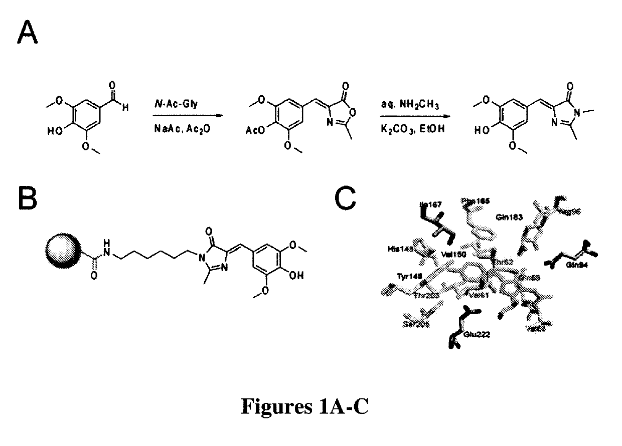
[0287]The most widely used approach for the synthesis of 4-arylidene-5-imidazolinones like those found in green fluorescent protein was first developed by Kojima et al. (“Fluorescent Properties of Model Chromophores of Tyrosine-66 Substituted Mutants of Aequorea Green Fluorescent Protein (GFP),”Tet. Lett. 39:5239-5242 (1998), which is hereby incorporated by reference in its entirety) and involves an Erlenmeyer azlactone formation between N-acetyl glycine and a 4-hydroxybenzaldehyde. The resulting azalactone is then subjected to aminolysis and subsequent cyclization under alkaline conditions to form the final 4-hydroxybenzylidene-5-imidazolinone (HBI).

[0288]Fundamentally the same synthesis was used here, except that a different substituted benzaldehyde was used to generate the novel fluorophore 3,5-dimethoxy-4-hydroxybenzylidene-5-imidazolinone (DMHBI). It was expected that the addition of these substituents would provide additional points of interaction for RN...

example 2

of Resin-Immobilized Fluorophore

[0291]To perform SELEX and pull out RNAs that could bind to the designed fluorophores of the present invention, a strategy was needed to immobilize the designed fluorophores on resin. Thus, a general synthesis mechanism for generating fluorophores containing an aminoalkyl linker was developed. The aminoalkyl linker could be linked to a commercially available NHS-activated resin (FIG. 1B).

[0292]The azalactone intermediate (prepared in Example 1) was first reacted with N-t-butyloxycarbonyl (BOC)-1,6-hexanediamine for aminolysis and subsequent cyclization. After silica gel purification of the BOC-protected product, the BOC moiety was removed with trifluoroacetic acid (TFA) treatment in dichloromethane. Silica gel purification yielded a pure fluorophore with a hexyl linker and a free amine to couple to an amine-reactive resin.

[0293]Linker-modified DMHBI was then coupled to NHS-activated agarose resin. The fluorophore was first dissolved in DMSO at a conce...

example 3

nce Characterization of Novel GFP-Mimetic Fluorophores

[0294]In GFP, the chromophore is held inside the protein β-barrel structure and rigidified by direct interactions with over a dozen amino acid residues (FIG. 1C). This inflexible positioning of the chromophore by the protein is the reason for its large fluorescent quantum yield. Similarly, the synthetic GFP chromophores 4-hydroxybenzilidene-1,2-dimethyl-imidazol-5-one (“HBDI”) is capable of bright fluorescence only when rigidified by solidified solvents (Niwa et al., “Chemical Nature of the Light Emitter of the Aequorea Green Fluorescent Protein,”Proc. Nat'l Acad. Sci. USA 93:13617-13622 (1996), which is hereby incorporated by reference in its entirety). Therefore, immobilization of DMHBI was performed to confirm whether DMHBI also exhibits this immobilization-dependent fluorescence that is seen in the native fluorophore. As an initial experiment DMHBI was first dissolved in ethanol and frozen in liquid nitrogen to create an etha...


PUM

PropertyMeasurementUnit
dissociation constantaaaaaaaaaa
pHaaaaaaaaaa

Abstract

The present invention relates to novel fluorophores and their use in combination with novel nucleic acid molecules, called aptamers, that bind specifically to the fluorophore and thereby enhance the fluorescence signal of the fluorophore upon exposure to radiation of suitable wavelength. Molecular complexes formed between the novel fluorophores, novel nucleic acid molecules, and their target molecules are described, and the use of multivalent aptamer constructs as fluorescent sensors for target molecules of interest are also described.

Description

[0001]This application is a national stage application under 35 U.S.C. § 371 of PCT Application No. PCT / US2010 / 024622, filed Feb. 18, 2010, which claims the priority benefit of U.S. Provisional Patent Application Ser. No. 61 / 207,897, filed Feb. 18, 2009, which is hereby incorporated by reference in its entirety.[0002]This invention was made with government support under grant number T32 CA062948 awarded by the National Institutes of Health. The U.S. government has certain rights in the invention.FIELD OF THE INVENTION[0003]The present invention relates to individual fluorophores, nucleic acid molecules (aptamers) that bind specifically to the fluorophore, molecular complexes containing the aptamers and fluorophores, as well as aptamers that bind specifically to a target molecule, and their use for in vitro or in vivo monitoring of the activity, trafficking, or degradation of various molecules, or the quantification thereof. The present invention also relates to methods and uses for ...

Claims


Application Information

Patent Timeline
Patent Type & Authority Patents(United States)
IPC IPC(8): G01N21/64C09B23/04C12N15/63C40B60/00C07D233/96A61K49/00C07D403/06
CPCC07D233/96A61K49/0032C09B23/04C07D403/06A61K49/0054
Inventor JAFFREY, SAMIE R.PAIGE, JEREMY S.
Owner CORNELL UNIVERSITY
Learn More