
Row planter with adjustable gauge wheels

a planter and adjustable technology, applied in the field of adjustable gauge wheels, can solve the problems of time-consuming operation, adversely affecting yield, and difficulty in operation, and achieve the effect of quick and easy adjustment of gauge wheels

Active Publication Date: 2019-05-28
HARVEST INT
View PDF50 Cites 2 Cited by
  • Summary
  • Abstract
  • Description
  • Claims
  • Application Information

AI Technical Summary

Benefits of technology

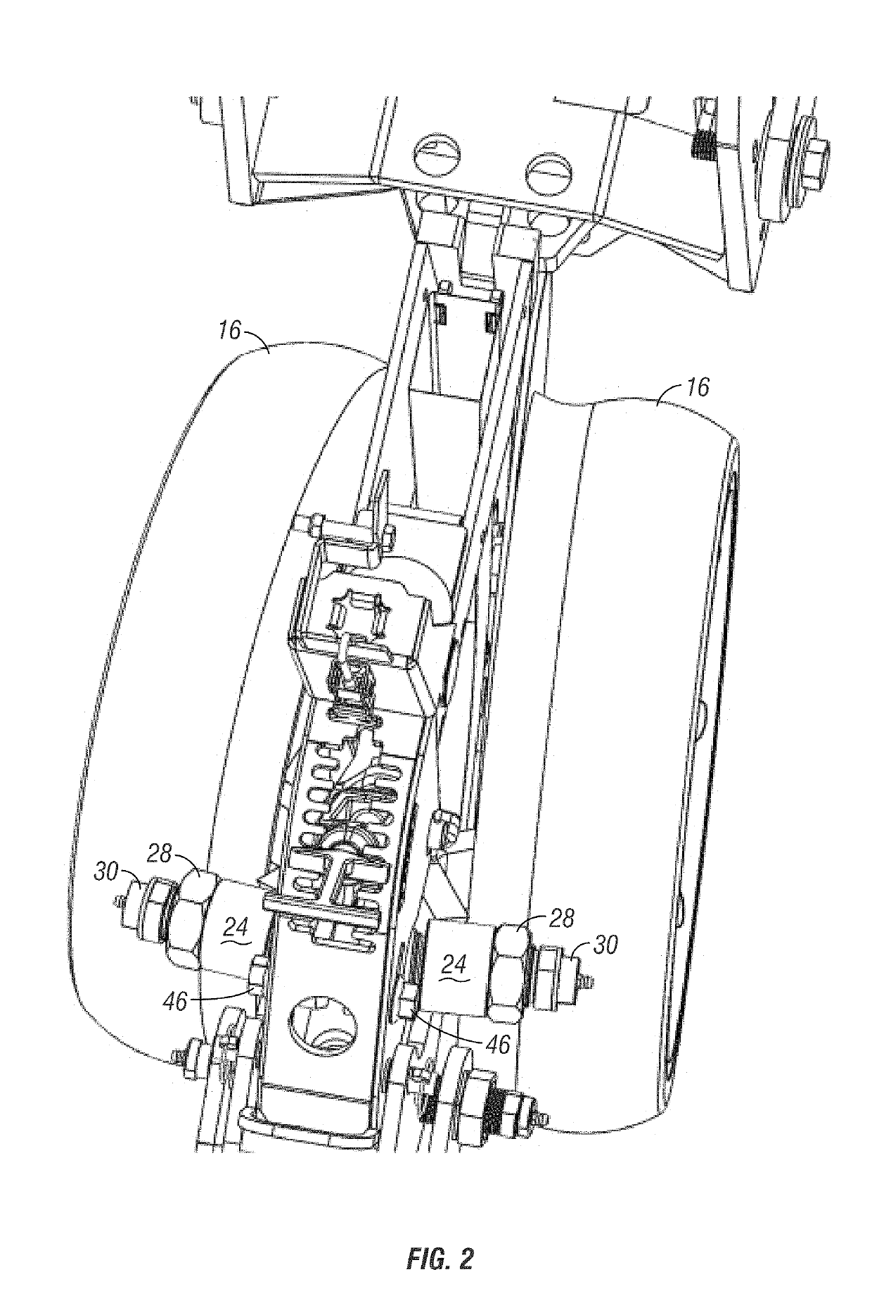
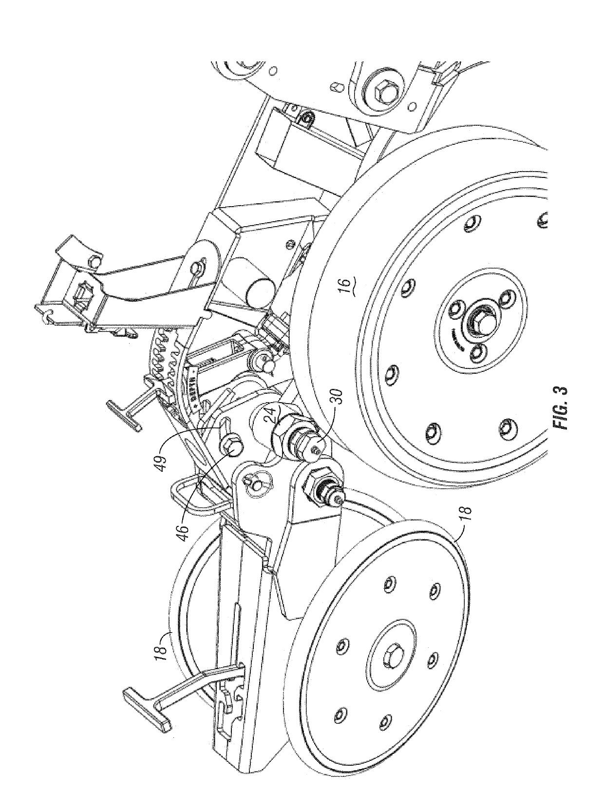
[0013]A row planter gauge wheel assembly is provided with the ability to quickly and easily adjust the gauge wheels relative to the opening discs on the row planter frame. Each gauge wheel is mounted on a pivotal arm. The upper end of each arm is mounted on a bushing assembly, including a pivot bushing extending into a threaded adjustment bushing. A nut on the adjustment bushing can be loosened to allow quick lateral adjustment of each gauge wheel.

Problems solved by technology

Over time, the bushings wear, which causes the gauge wheel angles to change and allow the gauge wheels to move away from the disc openers.
As the bushings wear, the disc openers spread apart, forming a gap between the disc openers.
The gap leads to deterioration of the V-shaped seed furrow profile, which is extremely undesirable, and which ultimately adversely affects yield.
This operation is time consuming and may be difficult if the wheel retaining bolt is corroded or the head is stripped.

Method used


Image

  • Row planter with adjustable gauge wheels
  • Row planter with adjustable gauge wheels
  • Row planter with adjustable gauge wheels

Examples


Embodiment Construction

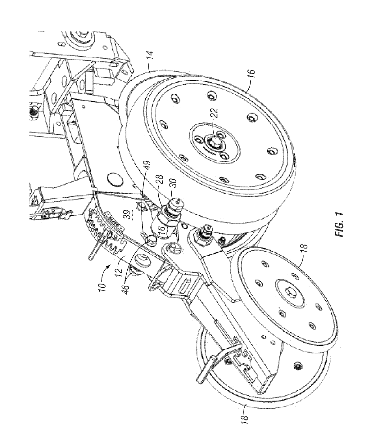
[0028]A row planter unit having the adjustable gauge wheels of the present invention is generally designated in the drawings by the reference numeral 10. The unit 10 includes a frame 12, a pair of disc openers (or opening discs) 14, a pair of gauge wheels 16, and a pair of closing wheels 18. The discs 14 and closing wheels 18 are conventional, and do not form a part of the present invention.

[0029]Applicant's invention is directed towards the gauge wheels 16, and more specifically, to the ability to adjust the camber and the lateral position of the gauge wheels 16.

[0030]As best seen in the partial exploded view of FIG. 5, each gauge wheel 16 is mounted on a lower end of an arm 20 via a bolt 22 which defines the rolling axis for the wheel. The upper end of the arm 20 is adjustably coupled to the frame 12 by a bushing assembly. More particularly, the upper end of the arm 20 has an internally threaded collar 24 which threadably receives a lateral adjustment bushing 26. The bushing 26 ha...


PUM


Abstract

Adjustable gauge wheels are provided on a row unit planter adjacent the opening disc. The wheels are adjustable laterally for proper spacing adjacent the discs. The camber of the gauge wheels relative to discs is also adjustable. The lateral adjustment is accomplished via a wear bushing and pivot bushing extending into the wear bushing for each gauge wheel. A grease zerk is provided on the end of each pivot bushing to supply grease to the inside of the adjustment wear bushing. The camber adjustment is accomplished via a slot in the row planter frame and bolts extending into arms on a pivotal member.

Description

CROSS-REFERENCE TO RELATED APPLICATION[0001]This application claims priority under 35 U.S.C. § 119 to provisional application Ser. No. 62 / 326,063, filed Apr. 22, 2016, herein incorporated by reference in its entirety.BACKGROUND OF THE INVENTIONS[0002]Row planter units are precision tools used in farming to plant high tech seeds at uniform depth and spacing to ensure the highest yield potential. To achieve maximum results, the row planter unit must be properly maintained and periodically adjusted.[0003]Row planter units typically include a pair of angularly disposed opening discs to form a V-shaped opening or furrow in the soil into which seeds are planted. The disc openers are followed by a pair of gauge wheels that control the depth of the furrow opened by the discs, and aid in holding the V-shaped profile of the furrow. The gauge wheels are mounted on pivoting arms, which include bushings. The gauge wheels are parallel to and are closely spaced to the discs, or contact the disc op...

Claims


Application Information

Patent Timeline
Patent Type & Authority Patents(United States)
IPC IPC(8): A01C7/20A01C5/06
CPCA01C5/064A01C7/203A01C5/068A01C7/201A01B71/04A01B63/163
Inventor SIVINSKI, JEFFREY ALANFRIESEN, BYRON J.
Owner HARVEST INT
Learn More