Air-shielded fuel injection assembly to facilitate reduced NOx emissions in a combustor system

a fuel injection assembly and air shielding technology, applied in the field of combustion systems, can solve the problems of accelerating the damage to the nozzle in a relatively short amount of time, the chemical reaction rate of combustion gases, etc., and achieve the effect of increasing the penetration of the fuel injection column and reducing the recirculation

Active Publication Date: 2019-05-14
GENERAL ELECTRIC CO
View PDF25 Cites 4 Cited by
  • Summary
  • Abstract
  • Description
  • Claims
  • Application Information

AI Technical Summary

Benefits of technology

[0008]In one aspect, an air-shielded fuel injector assembly for use in a combustion chamber of a turbine engine is provided. The air-shielded fuel injector assembly including a fuel manifold having a plurality of fuel injection ports and an air manifold having a plurality of air injection ports. Each fuel injection port is configured to introduce a fuel column into an annular cavity of a mixer assembly. Each air injection port is configured to introduce an air curtain to minimize recirculation upstream of the fuel injection column and increase penetration of the fuel injection column into the cavity.

Problems solved by technology

However, higher combustion temperatures also promote flame holding conditions in which the combustion flame migrates towards the fuel being supplied by nozzles, possibly causing accelerated damage to the nozzles in a relatively short amount of time.
Conversely, a lower combustion temperature associated with reduced fuel flow and / or part load operation (turndown) generally reduces the chemical reaction rates of the combustion gases, increasing the production of carbon monoxide and unburned hydrocarbons for the same residence time in the combustor.

Method used


Image

  • Air-shielded fuel injection assembly to facilitate reduced NO<sub>x </sub>emissions in a combustor system
  • Air-shielded fuel injection assembly to facilitate reduced NO<sub>x </sub>emissions in a combustor system
  • Air-shielded fuel injection assembly to facilitate reduced NO<sub>x </sub>emissions in a combustor system

Examples


Embodiment Construction

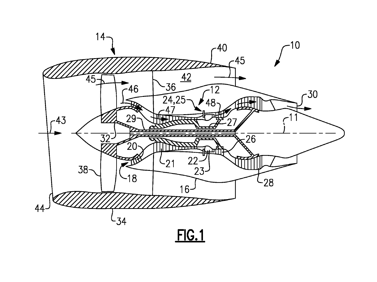
[0021]The exemplary methods and systems described herein overcome the structural disadvantages of known fuel injectors by providing optimal mixing of liquid and gaseous fuels with oxidizer in the combustor. It should also be appreciated that the term “first end” is used throughout this application to refer to directions and orientations located upstream in an overall axial flow direction of fluids with respect to a center longitudinal axis of a combustion chamber. It should be appreciated that the terms “axial” and “axially” are used throughout this application to refer to directions and orientations extending substantially parallel to a center longitudinal axis of a combustion chamber. It should also be appreciated that the terms “radial” and “radially” are used throughout this application to refer to directions and orientations extending substantially perpendicular to a center longitudinal axis of the combustion chamber. It should also be appreciated that the terms “upstream” and ...


PUM


Abstract

An air-shielded fuel injection assembly for use in a combustion chamber of a turbine assembly. The air-shielded fuel injection assembly generally includes a fuel manifold including a plurality of fuel injection ports and an air manifold including a plurality of air injection ports. Each of the plurality of fuel injection ports is configured to introduce a fuel column into an annular cavity of a mixer assembly. Each of the plurality of air injection ports is configured to introduce an air curtain about an associated fuel injection column to minimize recirculation upstream of the fuel injection column and increase penetration of the fuel injection column into the cavity. Also disclosed are a mixer assembly and a turbine assembly including the air-shielded fuel injection assembly.

Description

BACKGROUND[0001]The embodiments described herein relate generally to combustion systems, and more specifically, to systems that facilitate optimal mixing of liquid and gaseous fuels with oxidizer in a turbine combustor, such as gas turbine engine or liquid fuel aero-engine.[0002]Combustors are commonly used in industrial, power generation and aero operations to ignite fuel to produce combustion gases having a high temperature and pressure. For example, turbo-machines such as gas turbine engines or aero-engines, may include one or more combustors to generate power or thrust. A typical turbine system includes an inlet section, a compressor section, a combustion section, a turbine section, and an exhaust section. The inlet section cleans and conditions a working fluid (e.g., air) and supplies the working fluid to the compressor section. The compressor section increases the pressure of the working fluid and supplies a compressed working fluid to the combustion section. The combustion se...

Claims


Application Information

Patent Timeline
Patent Type & Authority Patents(United States)
IPC IPC(8): F23R3/28F02C7/22F23D14/64
CPCF23R3/286F02C7/222F23D14/64F23D2900/11002F05D2240/36F23D2206/10F05D2240/35
Inventor MONAHAN, SARAH MARIEHAYNES, JOEL MEIERJOSHI, NARENDRA DIGAMBERWALKER, DAVID JAMESLIM, JUNWOOVENKATESAN, KRISHNA KUMAR
Owner GENERAL ELECTRIC CO
Why Eureka
Try Eureka