Method for gas separation

a gas separation and gas technology, applied in the direction of separation processes, gaseous fuels, fuels, etc., can solve the problem that few psa designs can produce both high-quality results, and achieve the effect of high purity and recovery

Active Publication Date: 2019-05-07
GAS CAPTURE TECH +1
View PDF4 Cites 2 Cited by
  • Summary
  • Abstract
  • Description
  • Claims
  • Application Information

AI Technical Summary

Benefits of technology

[0012]It will be appreciated that where the product of the cycle feed time and the sum of the molar flow rates of the feed and reflux directed to the feed column equals the maximum number of moles that can be treated per bed per cycle, the method will provide the maximum degrees of productivity attainable for the first and second components, also referred to as the optimum gas separation.
[0014]Preferably, the reflux flow rate is a sufficiently large fraction of the feed flow rate such that both the enrichment factor for the heavy component (amount of heavy component in heavy product divided by that in the feed composition) and / or the stripping factor for the light component (amount of heavy component in the feed composition divided by that in the light product) are both no less than the pressure ratio used in the process. Advantageously, this provides both high purity and recovery for the products.

Problems solved by technology

However, one limitation in the application of PSA to gas purification is that few PSA designs can produce both a high-purity light product (raffinate) from the adsorption steps and an enriched secondary product (extract) during the regeneration steps.

Method used


Image

  • Method for gas separation
  • Method for gas separation
  • Method for gas separation

Examples


Embodiment Construction

[0038]The applicant has identified a process for optimising gas separation using a DR-PSA cycle for a given capital and operational cost. This description will utilise the separation of N2—CH4 mixtures by DR-PSA by way of an example to illustrate an embodiment of the invention.

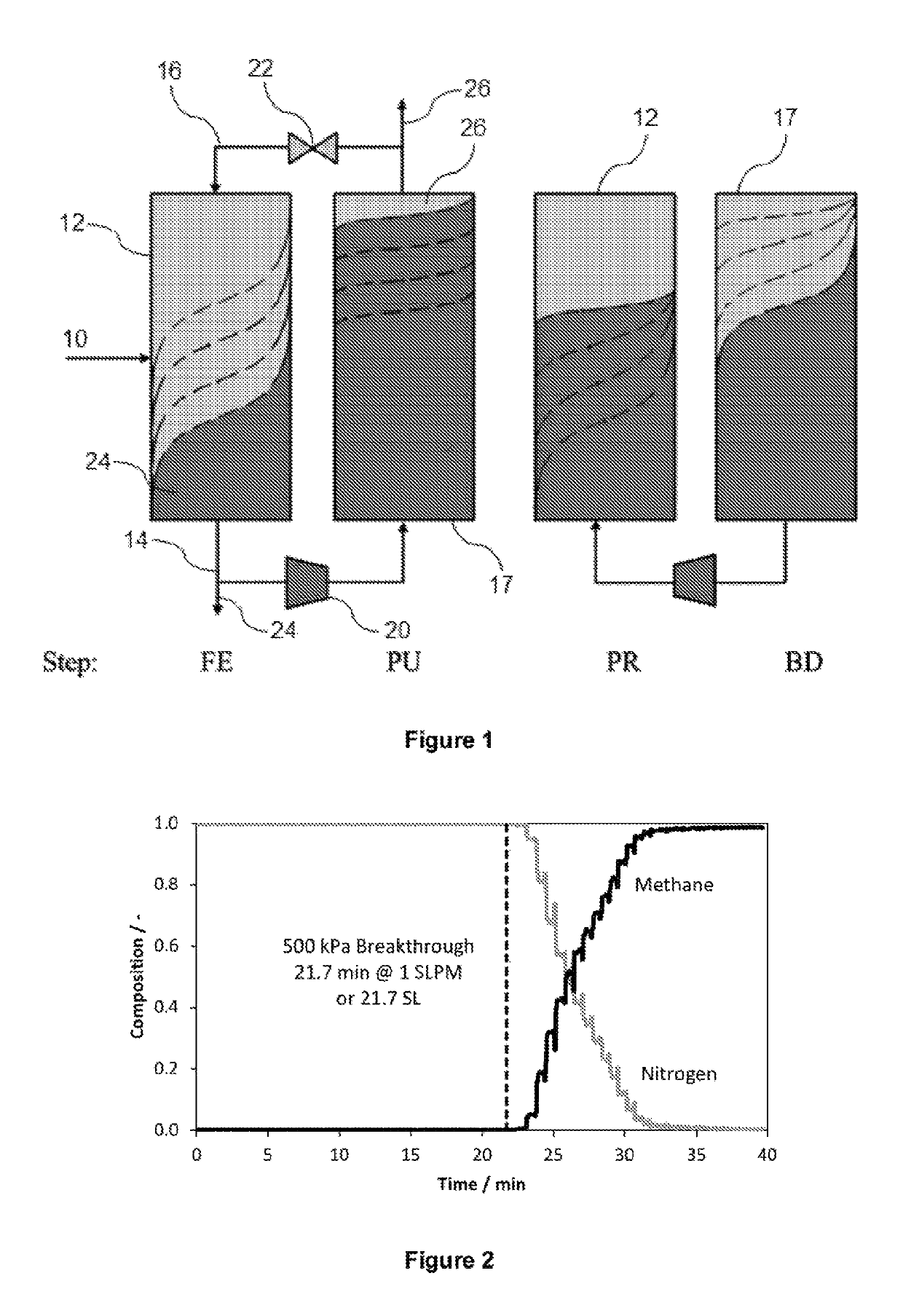
[0039]A typical DR-PSA cycle includes four basic steps: feed (FE), purge (PU), pressurization (PR) and blow down (BD), which occur in the pairs FE / PU and PR / BD so that every half-cycle is symmetric with each column's state swapping during the second half. The cycle can be configured so that the feed stream enters either the high pressure (PH) column or the low pressure (PL) column. Similarly, the cycle can be configured so that the pressure inversion is carried by transferring gas between the ends of the columns that is rich in either the heavy (more adsorbed) component (A), or in the light (less adsorbed) component (B). This leads to the four DR-PSA configurations, referred to as PH-A, PH-B, PL-A and PL-B.

[00...


PUM

PropertyMeasurementUnit
pressureaaaaaaaaaa
temperatureaaaaaaaaaa

Abstract

A method for controlling gas separation of a gas mixture comprising a first component and a second component, the method comprising contacting a feed containing the gas mixture with an adsorbent in a bed in a column in a dual reflux swing adsorption process such that a first component of a gas mixture attains or exceeds a desired purity and a second component of the gas mixture attains or exceeds a desired purity, wherein the mathematical product of the cycle feed time and the sum of the molar feed flow rate and the molar reflux flow rate directed to the column does not exceed the maximum number of moles that can be treated per bed per cycle and wherein the ratio of the first product flow rate to the feed flow rate is less than or equal to the first component's fraction of the feed, and the ratio of the second product flow rate to the feed flow rate is less than or equal to the second component's fraction of the feed.

Description

CROSS-REFERENCE TO RELATED APPLICATIONS[0001]The present application is a National Stage Application of PCT / AU2016 / 000129, filed Apr. 15, 2016, hereby incorporated by reference, which claims priority to Australian Application Number 2015901358, filed on Apr. 15, 2015.TECHNICAL FIELD[0002]A method for controlling gas separation using dual reflux swing adsorption.BACKGROUND ART[0003]The following discussion of the background art is intended to facilitate an understanding of the present invention only. The discussion is not an acknowledgement or admission that any of the material referred to is or was part of the common general knowledge as of the priority date of the application.[0004]Pressure swing adsorption (PSA) is an established technology employed to separate gas mixtures by exploiting differences in the adsorption capacities of the constituent gases, or, in a few industrial examples, by exploiting differences in sorption rates to achieve a kinetic selectivity. A continuous adso...

Claims


Application Information

Patent Timeline
Patent Type & Authority Patents(United States)
IPC IPC(8): B01D53/047C07C7/13C10L3/10B01D53/04
CPCB01D53/047C07C7/13C10L3/105B01D53/0462B01D2253/102B01D2253/108C10L2290/542B01D2256/245B01D2257/102B01D2258/05B01D2259/402B01D2259/40045B01D2259/40062B01D2253/116
Inventor MAY, ERIC FREEMANTLELI, GANGCHAN, KAMAN IDAHUANG, STANLEY HSING-WEISALEMAN, THOMAS LEROY HINTON
Owner GAS CAPTURE TECH
Why Eureka
Try Eureka