
Piece of display furniture for disglaying goods

a technology for dismantling goods and furniture, applied in the field of furniture, can solve the problems of large number of parts used, and especially the connection of surface elements being arranged next to each other or across the corner, in order to form a compartment, for example, to achieve the effect of reducing the number of parts used

Active Publication Date: 2019-05-07
LINDEN MICHAEL
View PDF32 Cites 1 Cited by
  • Summary
  • Abstract
  • Description
  • Claims
  • Application Information

AI Technical Summary

Benefits of technology

The patent describes a new design for furniture that uses magnets to attach parts together. The magnets are designed in a special way to make assembly easier and more accurate. The main benefit is that the magnets are narrower than the space they are inserted into, making it easier to fit them together without creating any attraction yet. This also allows for easier adaptation and positioning of the furniture parts. Overall, the design makes assembly easier and more precise using magnets.

Problems solved by technology

Even though the prior art also arrives at an easy assemblability of a display stand, the multitude of parts used and especially the connection of the surface elements being arranged next to each other or across a corner, in order to form a compartment for example, is still relatively large.

Method used


Image

  • Piece of display furniture for disglaying goods
  • Piece of display furniture for disglaying goods
  • Piece of display furniture for disglaying goods

Examples


Embodiment Construction

[0051]Individual technical features of the following described example embodiments can also be combined in combination with the above-described example embodiments as well as the features of the independent claim and any other claims to produce objects according to the invention. When advisable, functionally equivalent elements shall be given the same reference numbers.

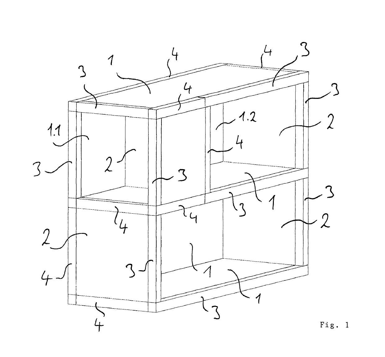
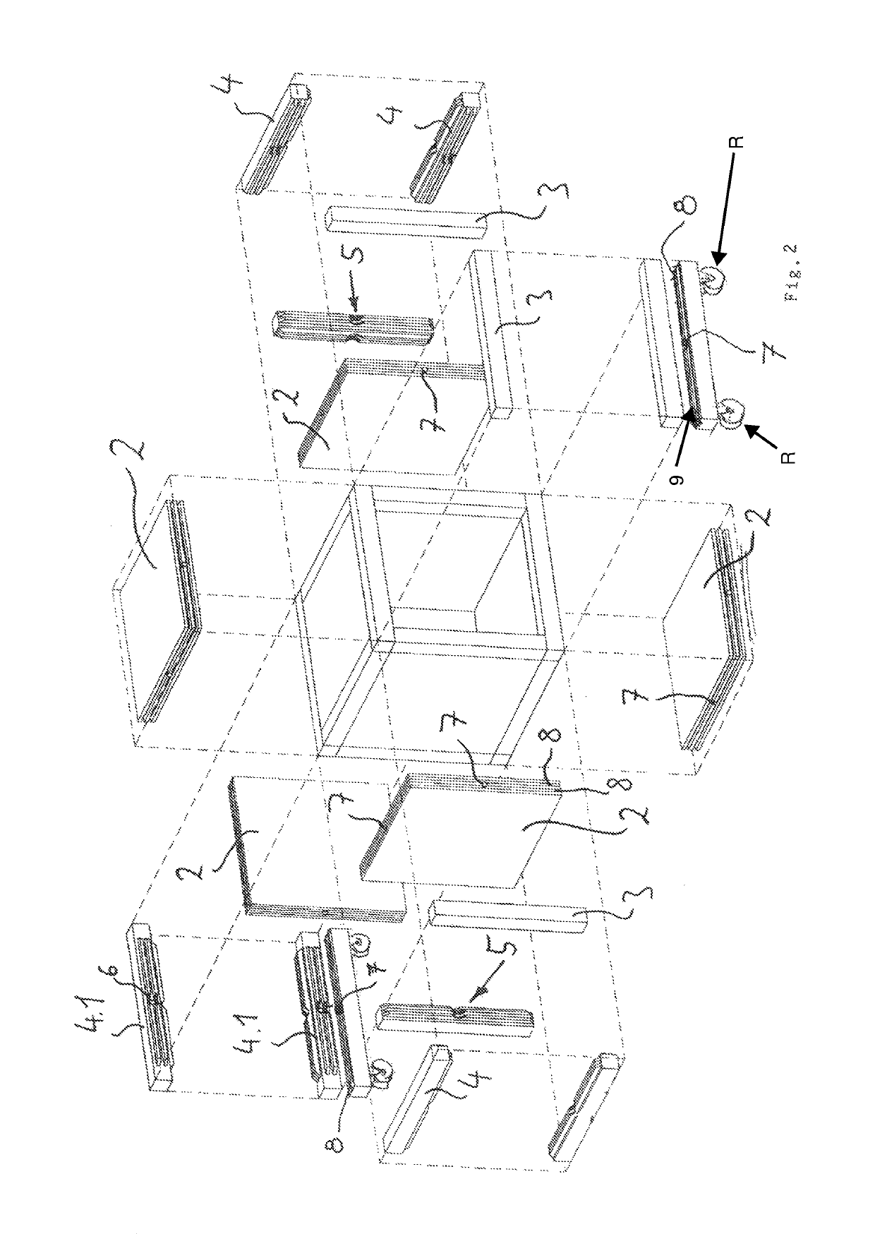
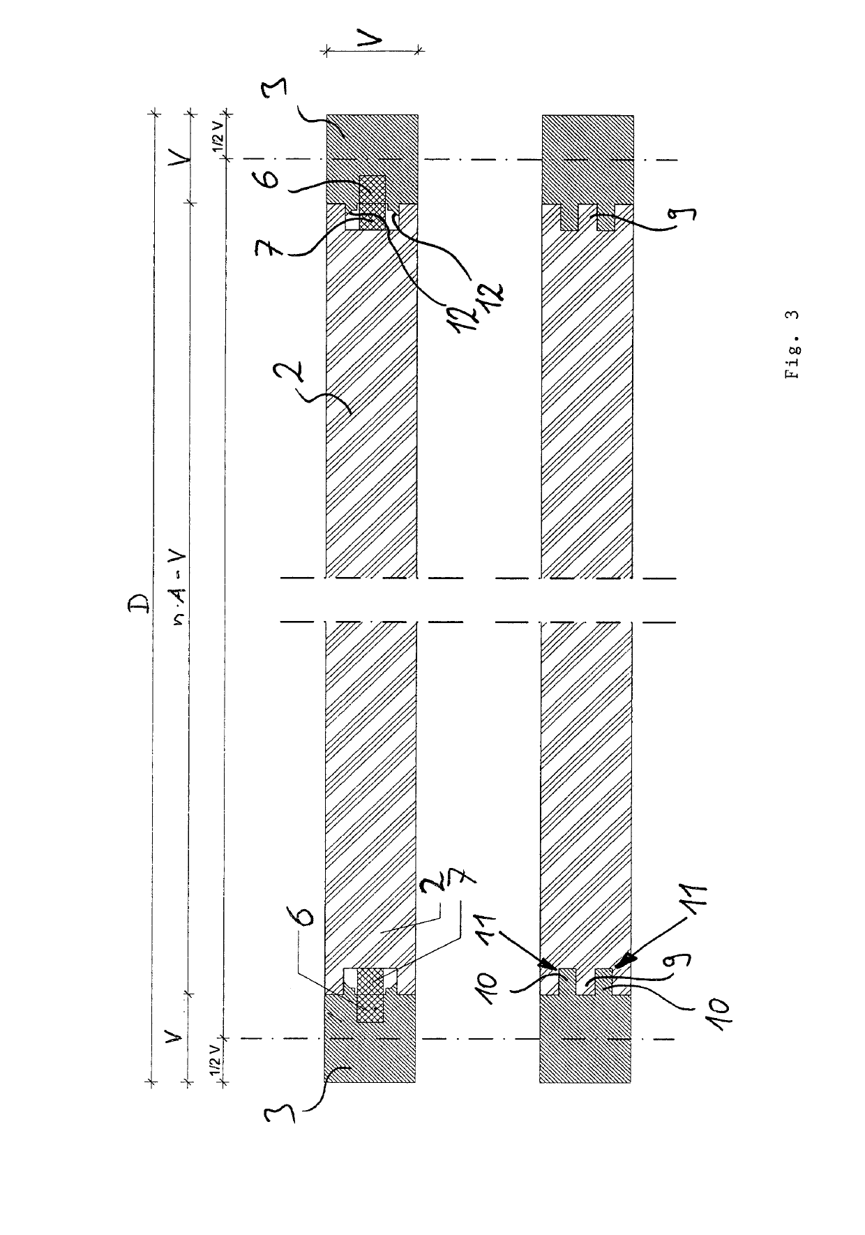
[0052]The furniture according to the invention, which in the present instance can be used as presentation furniture and especially as trade show shelving system, has according to FIG. 1 a series of different surfaces, connecting elements and closing elements, wherein surface elements are connected to connecting or closing elements via a groove structure present on surface elements in the form of double grooves and via a tongue structure present on connecting and closing elements in the form of a double tongue, and also via respective magnets.

[0053]In the present case, four identical surface elements 1 have been used t...


PUM

PropertyMeasurementUnit
Structureaaaaaaaaaa
Currentaaaaaaaaaa
Shapeaaaaaaaaaa

Abstract

A piece of furniture, in particular in the form of a piece of display furniture and preferably in the form of a piece of display furniture for displaying goods, further preferably a piece of modular-construction furniture in the form of a rack or cabinet, comprising a plurality of furniture elements, designed preferably as display-furniture elements, in the form of surface-area elements (1, 2) and connecting elements (4), it being possible for the latter to be fitted on narrow sides of the surface-area elements (1, 2), wherein the connection on the narrow sides, it being possible for said connection to be released without the use of tools, takes place via a tongue structure which can be introduced into a groove structure, preferably via a tongue which can be introduced into a groove or via a multiple tongue, designed at least in the form of a double tongue, which can be introduced into a multiple groove, designed at least in the form of a double groove, and wherein the furniture elements (1, 2, 4) are secured via the groove / tongue connection in a direction transverse to the surface-area extent of the surface-area element (1, 2) and, in addition, counter to the direction of introduction via the interaction of at least one magnet (6), arranged on one furniture element, and of a further magnetically attractable part, arranged on the adjacent furniture element, such that two surface-area elements (2, 1) which are arranged one beside the other or directly at a corner are connected via just one connecting element (4).

Description

BACKGROUND OF THE INVENTION[0001]The present invention concerns furniture, especially presentation furniture, preferably presentation furniture for merchandise, more preferably modularly constructable furniture in the form of a shelf or cabinet, comprising a plurality of furniture elements in the form of surface elements and connecting elements, which can be mounted on narrow sides of the surface elements.[0002]Furniture for merchandise, especially trade show shelving systems, is rather well known in the prior art. Examples of this which can be mentioned here are DE 10 109 590 B4 as well as U.S. Pat. No. 6,553,724 B1.[0003]Even though the prior art also arrives at an easy assemblability of a display stand, the multitude of parts used and especially the connection of the surface elements being arranged next to each other or across a corner, in order to form a compartment for example, is still relatively large. In addition, screw connections need to be loosened or tightened, and a mul...

Claims


Application Information

Patent Timeline
IPC IPC(8): A47B47/00A47F5/10A47F5/00A47F3/00F16B12/12F16B12/46
CPCA47B47/0041A47B47/0091A47F3/004A47F5/0018F16B12/125F16B12/46A47F5/10F16B2012/466A47B2230/07A47B2230/16F16B12/12F16B2012/463
Inventor LINDEN, MICHAEL
Owner LINDEN MICHAEL
Learn More