Solar battery module, and method of manufacturing solar battery module
a solar battery and module technology, applied in the field of solar battery modules, can solve the problems of large quantities of sealing resin that enters a softened state, deterioration of the characteristics and discoloration of sealing resin, so as to achieve the effect of simplifying the connection configuration and raising the degree of freedom for the connection configuration of the solar battery cells
- Summary
- Abstract
- Description
- Claims
- Application Information
AI Technical Summary
Benefits of technology
Problems solved by technology
Method used
Image

Examples
embodiment 1
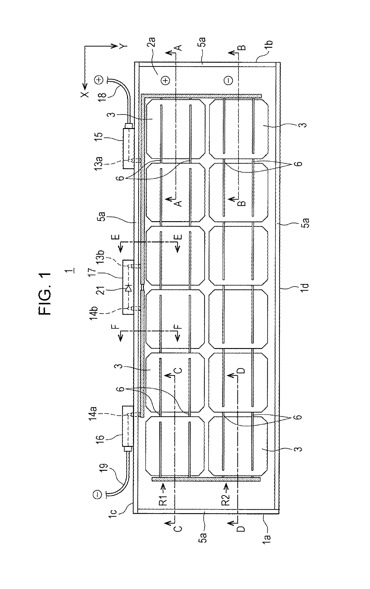
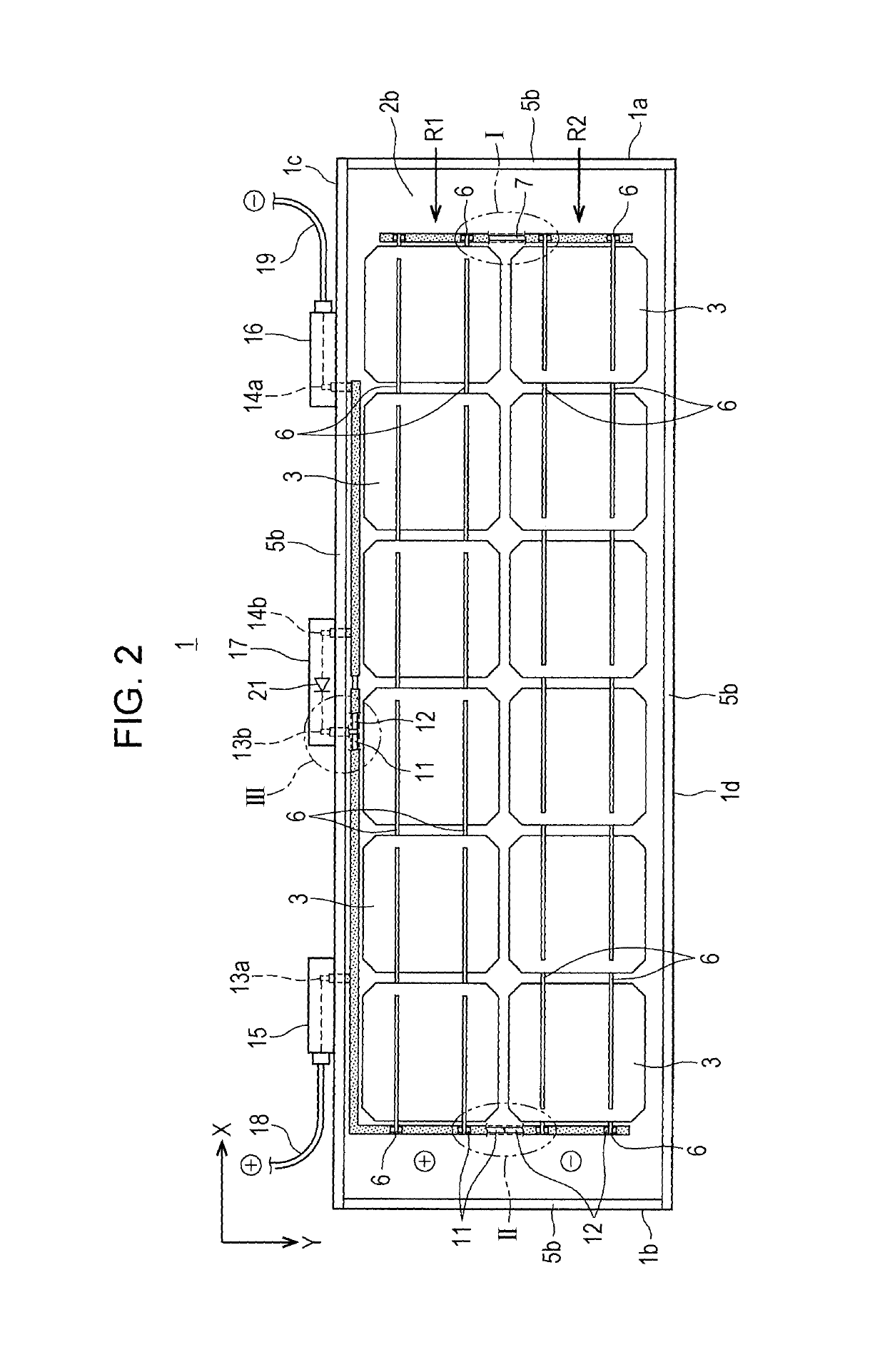
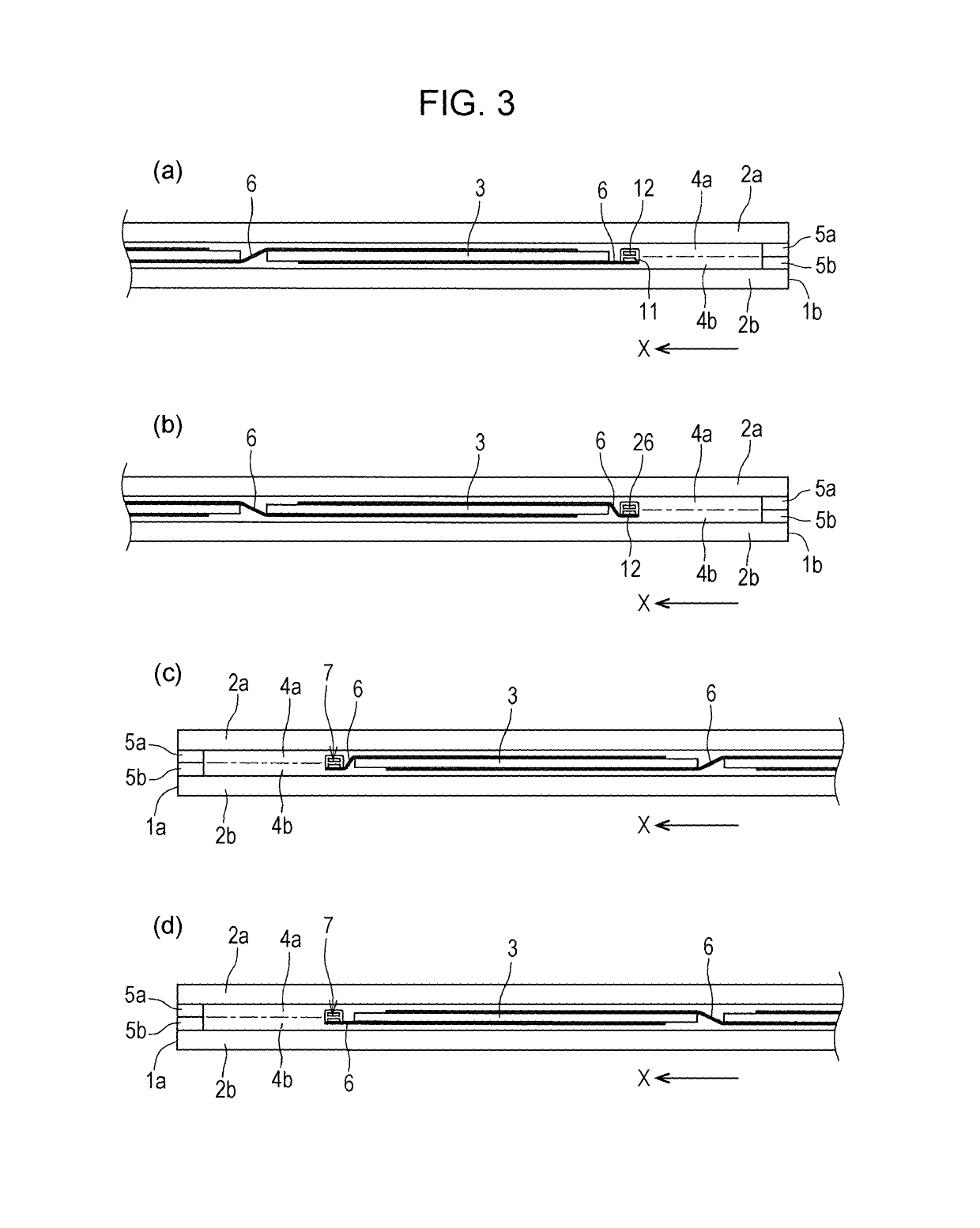
[0086]FIGS. 1 and 2 are a plan view and a rear view of a solar battery module relating to Embodiment 1 of the invention when viewed from a surface (light-receiving surface) side and from a rear surface side, respectively. In addition, FIGS. 3(a), 3(b), 3(c), and 3(d) are cross-sectional views taken along line A-A of FIG. 1, line B-B of FIG. 1, line C-C of FIG. 1, and line D-D of FIG. 1, respectively. In addition, FIGS. 4(a) and 4(b) are cross-sectional views taken along line E-E of FIG. 1 and line F-F of FIG. 1, respectively. In addition, FIG. 5 is a cross-sectional view illustrating the vicinity of an output terminal of the solar battery module of FIG. 1. In addition, FIGS. 6(a), 6(b), and 6(c) are enlarged views illustrating a portion I, a portion II, and a portion III in FIG. 2, respectively. Furthermore, in FIGS. 1 to 5, a horizontal direction is set as X, and a vertical direction is set as Y.
[0087]As shown in FIGS. 1 to 6, a solar battery module 1 has a configuration in which a...
embodiment 2
[0227]In addition, it is possible to temporarily fix the light-receiving surface side glass 106 and the non-light-receiving surface side glass 107 to each other through the protrusion prevention wall. Until now, there has been a problem that a positional deviation has tended to occur between the light-receiving surface side glass and the sealing resin, and between the sealing resin and the non-light-receiving surface side glass during transport of the solar battery module to the subsequent sealing process. However, the protrusion prevention wall with adhesiveness is disposed at opposite ends of the solar battery module, and thus it is possible to prevent the positional deviation during transport. As is the case with the example illustrated in FIG. 25 of Embodiment 2, a spacer 109 is disposed on outer sides of the pair of opposite ends of the solar battery module in which the protrusion prevention wall is disposed.
[0228]FIG. 31(c) is a view illustrating the sealing process. The seali...
embodiment 3
[0245]In the solar battery module 300, a lead-out electrode 141 is led out from between two protrusion prevention walls. The lead-out electrode 141 is led out from between the protrusion prevention walls, and thus it is possible to lead out the lead-out electrode to be approximately parallel with a light-receiving surface side glass and a non-light-receiving surface side glass without bending of the lead-out electrode at an end. As is the case with Embodiment 3, a portion of the lead-out electrode, which does not relate to electrical connection with a solar battery cell, may be coated with a protective film 144.
[0246]In addition, the protrusion prevention wall is disposed on all ends of the solar battery module, and thus almost no positional deviation of solar battery cells occurs. As a result, positional accuracy is further improved. According to this, it can be said that the design property of the solar battery module is further improved. In addition, a sealing resin does not prot...
PUM
 Abstract
Description
Claims
Application Information
 - R&D
- Intellectual Property
- Life Sciences
- Materials
- Tech Scout
- Unparalleled Data Quality
- Higher Quality Content
- 60% Fewer Hallucinations
Browse by: Latest US Patents, China's latest patents, Technical Efficacy Thesaurus, Application Domain, Technology Topic, Popular Technical Reports.
© 2025 PatSnap. All rights reserved.Legal|Privacy policy|Modern Slavery Act Transparency Statement|Sitemap|About US| Contact US: help@patsnap.com