
Subscriber station for a bus system and method for improving the error tolerance of a subscriber station of a bus system

a subscriber station and bus system technology, applied in the field of subscriber stations for bus systems and improving the error tolerance of subscriber stations, can solve the problems of unavoidable crosstalk between two or more can symbols, general damage to transfer quality, and higher bit error rate, and achieve the effect of transmission quality

Active Publication Date: 2019-04-23
ROBERT BOSCH GMBH
View PDF13 Cites 1 Cited by
  • Summary
  • Abstract
  • Description
  • Claims
  • Application Information

AI Technical Summary

Benefits of technology

The present invention relates to a subscriber station for a bus system that aims to improve transmission quality, particularly in adverse conditions. This subscriber station can be used in systems with faster cycles than a standard CAN bus system and can be implemented in the transmission or reception path of a CAN transceiver chipset. The method includes guaranteeing exclusive, collision-free access by the subscriber station to a bus line and pre-distorting the transmitted signal to achieve equilibration of the bus level on the transmission channel within the clock cycle of the signal. Overall, the invention enhances the reliability and performance of the subscriber station, especially in challenging bus environments.

Problems solved by technology

This can generally be detrimental to transfer quality, for example in the form of a higher bit error rate, when actually existing bus topologies are taken as the basis.
In reality, however, crosstalk between two or more CAN symbols is unavoidable.
These different times result in higher error probabilities in the receiving device, which can also be called a “receiver,” because of the slower transition from dominant to recessive bus level.
Because an increase in the data rate is achieved in CAN-FD in particular by shortening the symbol duration in the data section, which is transmitted once arbitration is complete, this property could limit the utilization scenarios for the bus system.
The distance between the received signal and the decider threshold is very greatly decreased in this context, so that overlaid noise interference can, with a very much higher probability, result in an incorrect detection in the CAN transmission / reception device.

Method used


Image

  • Subscriber station for a bus system and method for improving the error tolerance of a subscriber station of a bus system
  • Subscriber station for a bus system and method for improving the error tolerance of a subscriber station of a bus system
  • Subscriber station for a bus system and method for improving the error tolerance of a subscriber station of a bus system

Examples


Embodiment Construction

[0038]Unless otherwise indicated, identical or functionally identical elements are labeled in the Figures with the same reference characters.

Description Of The Exemplifying Embodiments

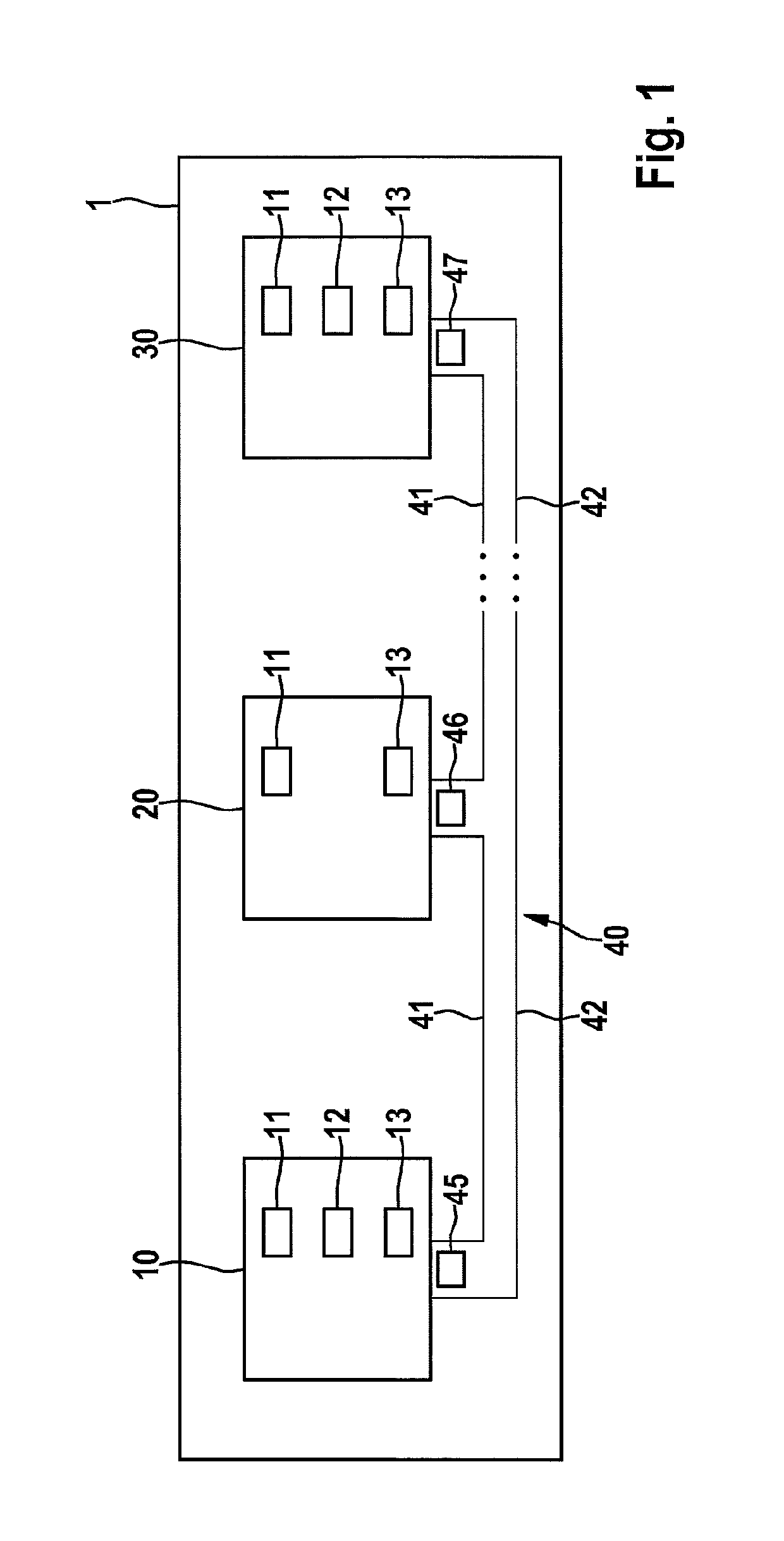
[0039]FIG. 1 shows a bus system 1 that can be, for example, a CAN bus system, a CAN-FD bus system, etc. Bus system 1 can be utilized in a vehicle, in particular a motor vehicle, an aircraft, etc., or in a hospital, etc.

[0040]In FIG. 1, bus system 1 has a plurality of subscriber stations 10, 20, 30 that are each connected to a bus line 40 having a first bus wire 41 and a second bus wire 42. Bus wires 41, 42 can also be called CAN High (C_H) and CAN Low (C_L) and serve to couple in the dominant level in the transmission state. Messages 45, 46, 47 in the form of signals can be transferred via bus line 40 between the individual subscriber stations 10, 20, 30. Subscriber stations 10, 20, 30 can be, for example, control units or indicating apparatuses of a motor vehicle.

[0041]As shown in FIG. 1, subscriber s...


PUM


Abstract

A subscriber station for a bus system, and a method for improving the error tolerance of a subscriber station of a bus system, are presented. The subscriber station encompasses a transmission / reception device for transmitting a signal via the bus system to a further subscriber station and for receiving a signal via the bus system, in which exclusive, collision-free access by a subscriber station to a bus line of the bus system is guaranteed at least at times; and a modification device for modifying the transmission properties of a transmission path of the transmission / reception device and / or the reception properties of a reception path of the transmission / reception device.

Description

FIELD OF THE INVENTION[0001]The present invention relates to a subscriber station for a bus system and to a method for improving the error tolerance of a subscriber station of a bus system, in which, in particular, error tolerance in the context of an information transfer on a bus system is improved even in unfavorable conditions such as those that exist, for example, as a result of branches, incorrect terminations, misadaptation, or pinched wiring in the bus system.BACKGROUND INFORMATION[0002]The CAN bus system has become widespread for communication between sensors and control units. In the CAN bus system, messages are transferred using the CAN protocol as described in the CAN specification in ISO 11898. Techniques such as CAN-FD, in which messages can be transferred in accordance with “CAN with Flexible Data Rate, Specification Version 1.0” (source: http: / / www.semiconductors / bosch.de), etc., have also recently been proposed for this. With such technologies, the maximum possible d...

Claims


Application Information

Patent Timeline
Patent Type & Authority Patents(United States)
IPC IPC(8): G06F13/42H04L25/02G06F11/07H04L12/40
CPCG06F13/4221G06F11/0745G06F11/0793H04L25/0272H04L2012/40215
Inventor NICKEL, PATRICK
Owner ROBERT BOSCH GMBH
Learn More