Side-mount type engine control apparatus

a control apparatus and side mount technology, applied in the direction of mechanical control devices, instruments, vessel construction, etc., can solve the problems of large force on the side mount, the control apparatus of the top mount cannot be used in a small boat, and the size of the mount is limited, so as to achieve the effect of easy operation of the control lever

Active Publication Date: 2019-04-09
NHK SPRING CO LTD
View PDF14 Cites 2 Cited by
  • Summary
  • Abstract
  • Description
  • Claims
  • Application Information

AI Technical Summary

Benefits of technology

[0009]An object of the present invention is to provide a side-mount type engine control which can easily operate a control lever, and includes a housing which is structured to be slim and compact.
[0011]According to this embodiment, it is possible to provide a side-mount type engine control apparatus which is capable of performing a throttle operation, etc., of the control lever with relatively small force, has good operability, and is configured to be slim and compact. Moreover, the engine control apparatus of the present embodiment can be mounted on a port-side mounting surface or a starboard-side mounting surface of a mount provided on a hull.

Problems solved by technology

However, a top-mount type engine control apparatus may not be used in a small boat in which the size of the mount is limited.
However, in a case of a boat in which a high-power engine is mounted on a small hull, the side-mount type engine control apparatus is required to operate mechanical transmission cables with great force.
Accordingly, shifting or throttle operability is deteriorated.
Accordingly, it is difficult to arrange the bolt in the housing such that it does not interfere with the movable members.
However, a problem in the above is that the shape of the housing having the flange is restricted, and moreover, a contour of the housing is enlarged.

Method used


Image

  • Side-mount type engine control apparatus
  • Side-mount type engine control apparatus
  • Side-mount type engine control apparatus

Examples


Embodiment Construction

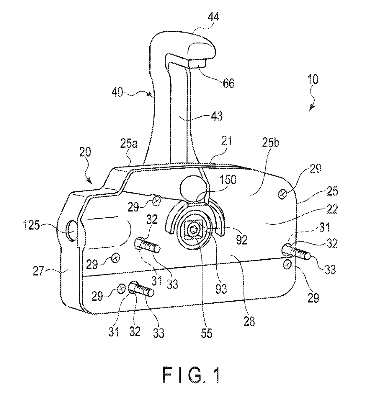
[0027]A side-mount type engine control apparatus 10 according to one embodiment will be described with reference to FIGS. 1 to 9.

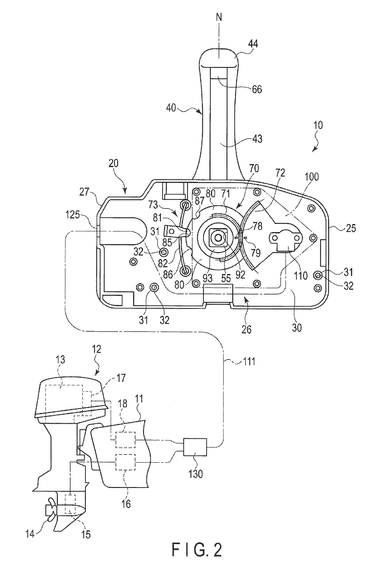
[0028]FIG. 1 illustrates the side-mount type engine control apparatus 10. FIG. 2 illustrates the interior of the engine control apparatus 10, and an example of an outboard motor 12 mounted in the rear of a hull 11. The outboard motor 12 includes a propeller 14, a shift mechanism 15, a shift actuator 16, a throttle mechanism 17, a throttle actuator 18, etc. The propeller 14 rotates with an engine (an internal-combustion engine) 13 used as a source of power.

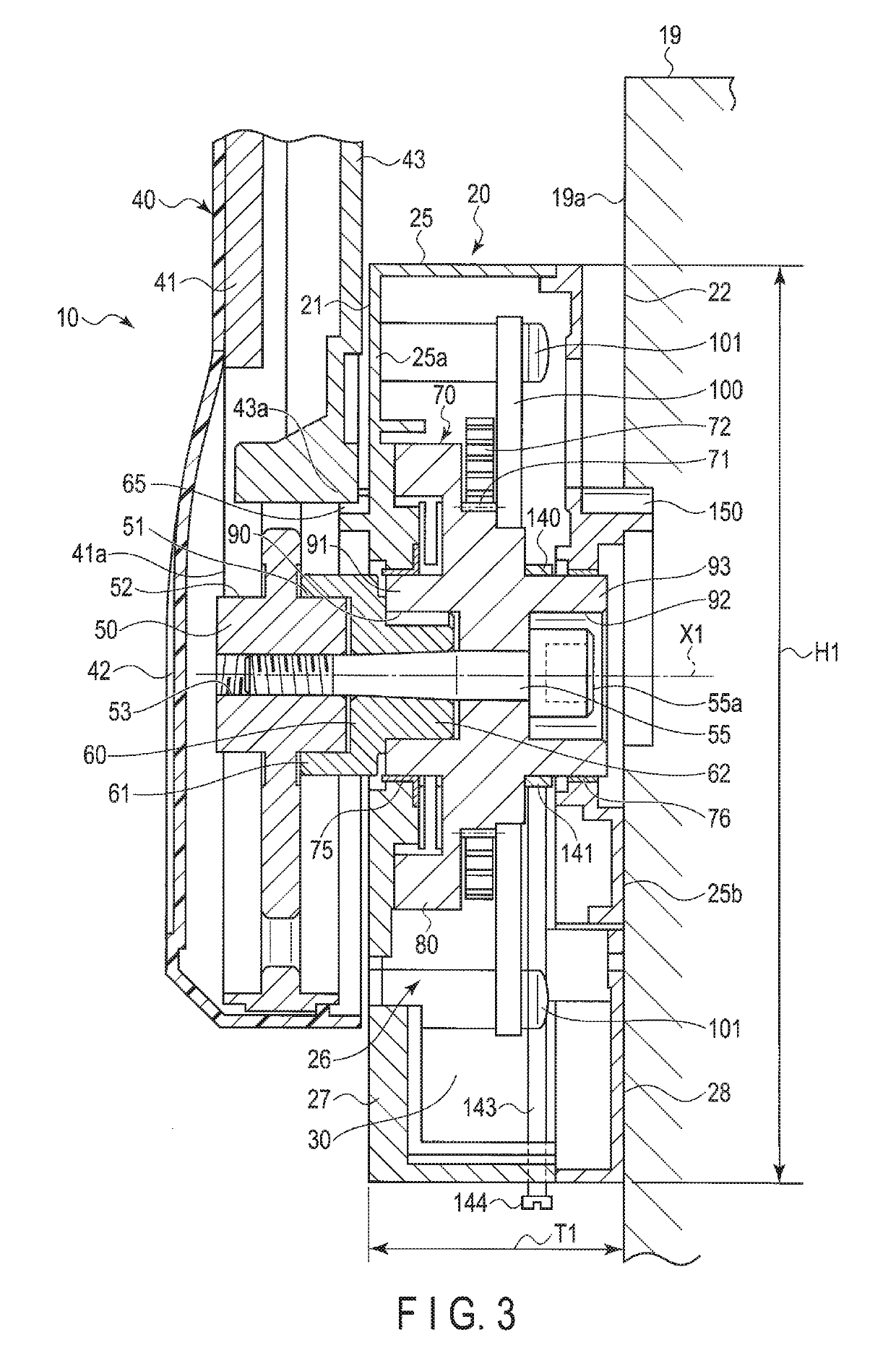
[0029]FIG. 3 is a vertical sectional view of a part of the engine control apparatus 10. A mount 19 is provided on the hull. The engine control apparatus 10 is mounted on a port-side mounting surface 19a of the mount 19. The mount 19 is provided near a cockpit of the hull. The engine control apparatus 10 includes an apparatus body 20, and a control lever 40. The control lever 40 can be mounted on either si...


PUM


Abstract

An engine control apparatus includes an apparatus body, and a control lever. The apparatus body includes a housing, an axis unit including a drive gear, a driven gear, and an angle sensor. A plurality of fixing portions are provided on the housing. A through-hole is formed in the fixing portion. The through-hole is communicated with a first side wall and a second side wall of the housing. The housing is fixed to a port-side mounting surface or a starboard-side mounting surface by a screw member inserted into the through-hole. When the control lever is operated, the drive gear and the driven gear are rotated in accordance with an angle of operation. A rotational angle of the driven gear is detected by an angle sensor.

Description

CROSS-REFERENCE TO RELATED APPLICATIONS[0001]This application is based upon and claims the benefit of priority from prior Japanese Patent Application No. 2017-013161, filed Jan. 27, 2017, the entire contents of which are incorporated herein by reference.BACKGROUND OF THE INVENTION[0002]1. Field of the Invention[0003]The present invention relates to a side-mount type engine control apparatus for performing a throttle operation, etc., of an engine of a boat, for example.[0004]2. Description of the Related Art[0005]In an engine system for a boat including an engine (an internal-combustion engine) as a power source, an engine control apparatus which performs a shift operation and a throttle operation by a control lever is known. In JPH4-193696 A (Patent Literature 1) and JP 2015-166225 A (Patent Literature 2), a side-mount type engine control apparatus is described. A mount is provided on a hull. A housing of the side-mount type engine control apparatus is fixed to a mounting surface of...

Claims


Application Information

Patent Timeline
Patent Type & Authority Patents(United States)
IPC IPC(8): B63H21/21F16H59/10G05G5/06B63H20/14F16H59/02G05G5/04G05G1/04G05G5/02F02B61/04F02D11/04
CPCB63H21/213F16H59/0278F16H59/105G05G1/04G05G5/02G05G5/04G05G5/06G05G5/065B63H21/28Y10T74/20612B63H2021/216F02B61/045F02D11/04Y10T74/2011Y10T74/20232B63H20/10
Inventor OZAKI, TAISHI
Owner NHK SPRING CO LTD
Why Eureka
Try Eureka