Exhaust gas control system for internal combustion engine and control method for internal combustion engine

a control system and exhaust gas technology, applied in the direction of electric control, combustion engines, machines/engines, etc., can solve problems such as the inability to perform malfunction diagnosis

Active Publication Date: 2019-04-02
TOYOTA JIDOSHA KK
View PDF5 Cites 4 Cited by
  • Summary
  • Abstract
  • Description
  • Claims
  • Application Information

AI Technical Summary

Benefits of technology

[0011]According to the above-described configuration, for the malfunction diagnosis for diagnosing the three-way catalyst, the upstream sensor, or the downstream sensor, the second air-fuel ratio control is executed when the temperature of the three-way catalyst is equal to or higher than the predetermined diagnosis temperature. The predetermined diagnosis temperature is a temperature at which the three-way catalyst in a normal state is sufficiently activated. Then, the second air-fuel ratio control is executed when the temperature of the three-way catalyst is equal to or higher than the diagnosis temperature. With this, it is possible to perform the malfunction diagnosis of the three-way catalyst, the upstream sensor, or the downstream sensor based on a way of transition of the detection value of the upstream sensor or the downstream sensor when the second air-fuel ratio control is executed.
[0014]Accordingly, it is possible to prevent the temperature of the three-way catalyst from decreasing below the diagnosis temperature after the execution of the first air-fuel ratio control is interrupted. For this reason, in a case where there is a request for the malfunction diagnosis while the first air-fuel ratio control is being executed, it is possible to more suitably execute the malfunction diagnosis.
[0015]In the above-described exhaust gas control system, the electronic control unit may be configured to perform the malfunction diagnosis by executing the second air-fuel ratio control in response to the electronic control unit interrupts the execution of the first air-fuel ratio control after a state in which the estimated reference catalyst temperature is equal to or higher than the diagnosis temperature is continued for a first predetermined period or longer. The first predetermined period is a period in which it can be determined that the reference catalyst temperature of the three-way catalyst is stable and becomes equal to or higher than the diagnosis temperature. In this way, the execution of the first air-fuel ratio control is interrupted after the state in which the reference catalyst temperature of the three-way catalyst is equal to or higher than the diagnosis temperature is continued for the first predetermined period or longer, whereby it is possible to prevent the temperature of the three-way catalyst from decreasing below the diagnosis temperature with a high probability after the execution of the first air-fuel ratio control is interrupted.
[0018]According to the above-described configuration, as in the above-described first aspect, it is possible to prevent the temperature of the three-way catalyst from decreasing below the diagnosis temperature after the execution of the first air-fuel ratio control is interrupted. For this reason, in a case where there is a request for the malfunction diagnosis while the first air-fuel ratio control is being executed, it is possible to more suitably execute the malfunction diagnosis.
[0019]In the second aspect, the electronic control unit may be configured to perform the malfunction diagnosis by executing the second air-fuel ratio control in response to the electronic control unit interrupts the execution of the first air-fuel ratio control after a state in which the temperature of the three-way catalyst is equal to or higher than the interruption temperature while the first air-fuel ratio control is being executed is continued for a second predetermined period or longer. The second predetermined period is a period in which it can be determined that the temperature of the three-way catalyst is stable and becomes equal to or higher than the interruption temperature while the first air-fuel ratio control being executed. In this way, the execution of the first air-fuel ratio control is interrupted after the state in which the temperature of the three-way catalyst is equal to or higher than the interruption temperature while the first air-fuel ratio control is being executed is continued for the second predetermined period or longer, it is possible to prevent the temperature of the three-way catalyst from decreasing below the diagnosis temperature with a high probability after the execution of the first air-fuel ratio control is interrupted.

Problems solved by technology

In this case, it is not possible to perform malfunction diagnosis.

Method used


Image

  • Exhaust gas control system for internal combustion engine and control method for internal combustion engine
  • Exhaust gas control system for internal combustion engine and control method for internal combustion engine
  • Exhaust gas control system for internal combustion engine and control method for internal combustion engine

Examples


Embodiment Construction

[0030]Hereinafter, a specific embodiment of the disclosure will be described based on the drawings. The dimensions, materials, shapes, relative arrangements, and the like of constituent parts described in the embodiments are not intended to limit the technical scope of the disclosure to these alone in particular as long as there are not specific statements.

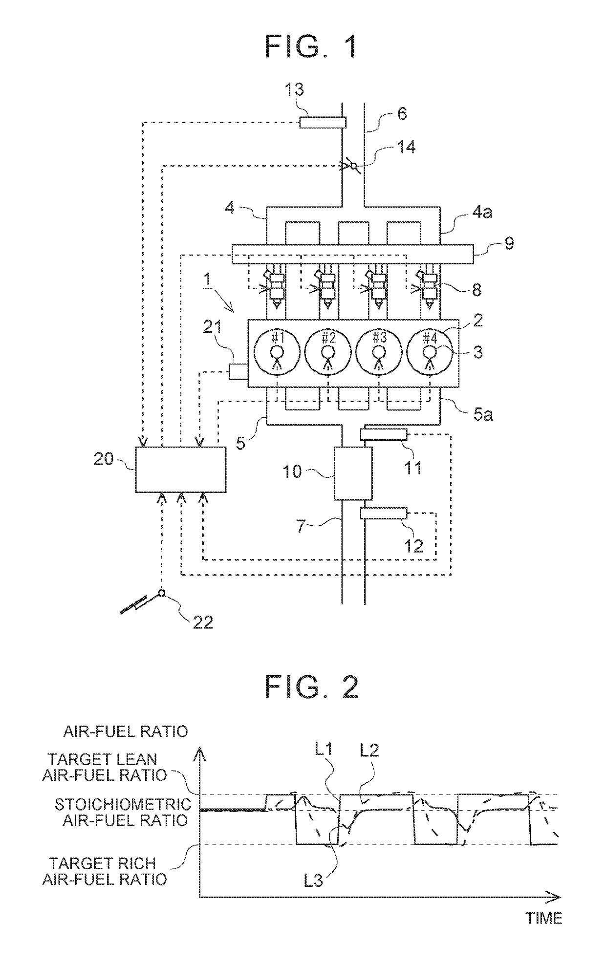
[0031]First, a first embodiment will be described. FIG. 1 is a diagram showing the schematic configuration of an internal combustion engine according to this embodiment and an intake and exhaust system thereof. An internal combustion engine 1 is a gasoline engine for vehicle drive. The internal combustion engine 1 is an in-line four-cylinder engine having four cylinders 2. Each cylinder 2 of the internal combustion engine 1 is provided with an ignition plug 3.

[0032]An intake manifold 4 and an exhaust manifold 5 are connected to the internal combustion engine 1. Then, each intake branch pipe 4a of the intake manifold 4 is connected...


PUM


Abstract

In the exhaust gas control system, the electronic control unit is configured to execute first air-fuel ratio control for controlling an air-fuel ratio of an air-fuel mixture in a part of cylinders to a lean air-fuel ratio and controlling an air-fuel ratio of an air-fuel mixture in the other part of the cylinders to a rich air-fuel ratio is executed. The electronic control unit is configured to execute second air-fuel ratio control to perform malfunction diagnosis. The electronic control unit is configured to execute second air-fuel ratio control when the execution of the first air-fuel ratio control is interrupted after the temperature of the three-way catalyst becomes equal to or higher than the diagnosis temperature.

Description

INCORPORATION BY REFERENCE[0001]The disclosure of Japanese Patent Application No. 2016-126812 filed on Jun. 27, 2016 including the specification, drawings and abstract is incorporated herein by reference in its entirety.BACKGROUND1. Technical Field[0002]The present disclosure relates to an exhaust gas control system for an internal combustion engine and a control method for an internal combustion engine.2. Description of Related Art[0003]In an exhaust gas control system for an internal combustion engine including a three-way catalyst provided in an exhaust passage, a technique for controlling an air-fuel ratio for each cylinder of the internal combustion engine in order to increase the temperature of the three-way catalyst is known. In air-fuel ratio control for increasing the catalyst temperature, an air-fuel ratio of an air-fuel mixture in a part of the cylinders is controlled to a lean air-fuel ratio leaner than a stoichiometric air-fuel ratio, and an air-fuel ratio of an air-fue...

Claims


Application Information

Patent Timeline
Patent Type & Authority Patents(United States)
IPC IPC(8): F02D21/08F02D41/00
CPCF02D21/08F02D41/0055F02D41/0052F02D41/0082F02D41/025F02D41/1441F02D41/1454F02D41/1475F02D41/1495F02D2200/0802F02D2200/0804Y02T10/12
Inventor NAKAMURA, TAKASHIMYOJO, KEIICHISHOGENJI, YOSHIYUKIKOBASHI, NORIYASUNOSE, YUKIIKUTA, EIJI
Owner TOYOTA JIDOSHA KK
Why Eureka
Try Eureka