
Clamp for securing and electrically bonding solar panels to a rail support

a solar panel and rail support technology, applied in the direction of photovoltaic supports, heat collector mounting/supports, lighting and heating apparatus, etc., can solve the problems of increasing the installation process, requiring special tools, and affecting the installation process, and achieve the effect of sufficient resilien

Active Publication Date: 2019-03-26
IRONRIDGE
View PDF55 Cites 13 Cited by
  • Summary
  • Abstract
  • Description
  • Claims
  • Application Information

AI Technical Summary

Benefits of technology

The invention provides a clamp that can securely attach a flange to a rail support by gripping the upper and lower surfaces of the flange. The clamp has a front end and a rear end. The rear end is designed to have a lot of flexibility so that it can securely hold the flange in place. This makes it easier to attach and support heavy loads.

Problems solved by technology

The installation of solar panel arrays on residential roofs can be arduous and time-consuming.
Depending on the array design, the components required to install the array can make the installation process even more difficult.
Many of the assembly components require special tools or are generally difficult to install because they are utilized after the solar panels modules are arranged or positioned on their support elements.
A limitation of these types of mid-clamps is that they are exposed on top of the panels and can be aesthetically unsightly if used along the perimeter of the array.
Existing clamps are either unsatisfying in providing a way to secure solar panel modules to rails with guides or slots located on the top of the rails.

Method used


Image

  • Clamp for securing and electrically bonding solar panels to a rail support
  • Clamp for securing and electrically bonding solar panels to a rail support
  • Clamp for securing and electrically bonding solar panels to a rail support

Examples


Embodiment Construction

[0053]In the following description, and for the purposes of explanation, numerous specific details are provided to thoroughly understand the various aspects of the invention. It will be understood, however, by those skilled in the relevant arts, that the present invention may be practiced without these specific details. In other instances, known structures and devices are shown or discussed more generally in order to avoid obscuring the invention. In many cases, a description of the operation is sufficient to enable one to implement the various forms of the invention, particularly when the operation is to be implemented in software. It should be noted that there are many different and alternative configurations, devices and technologies to which the disclosed embodiments may be applied. The full scope of the invention is not limited to the example(s) that are described below.

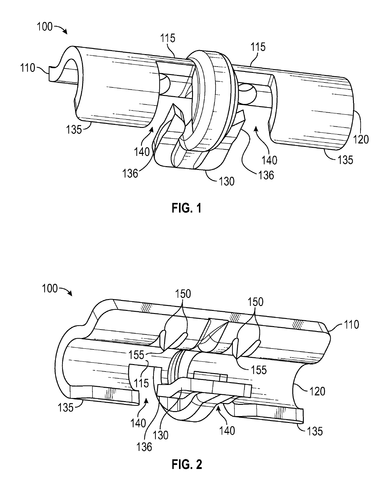
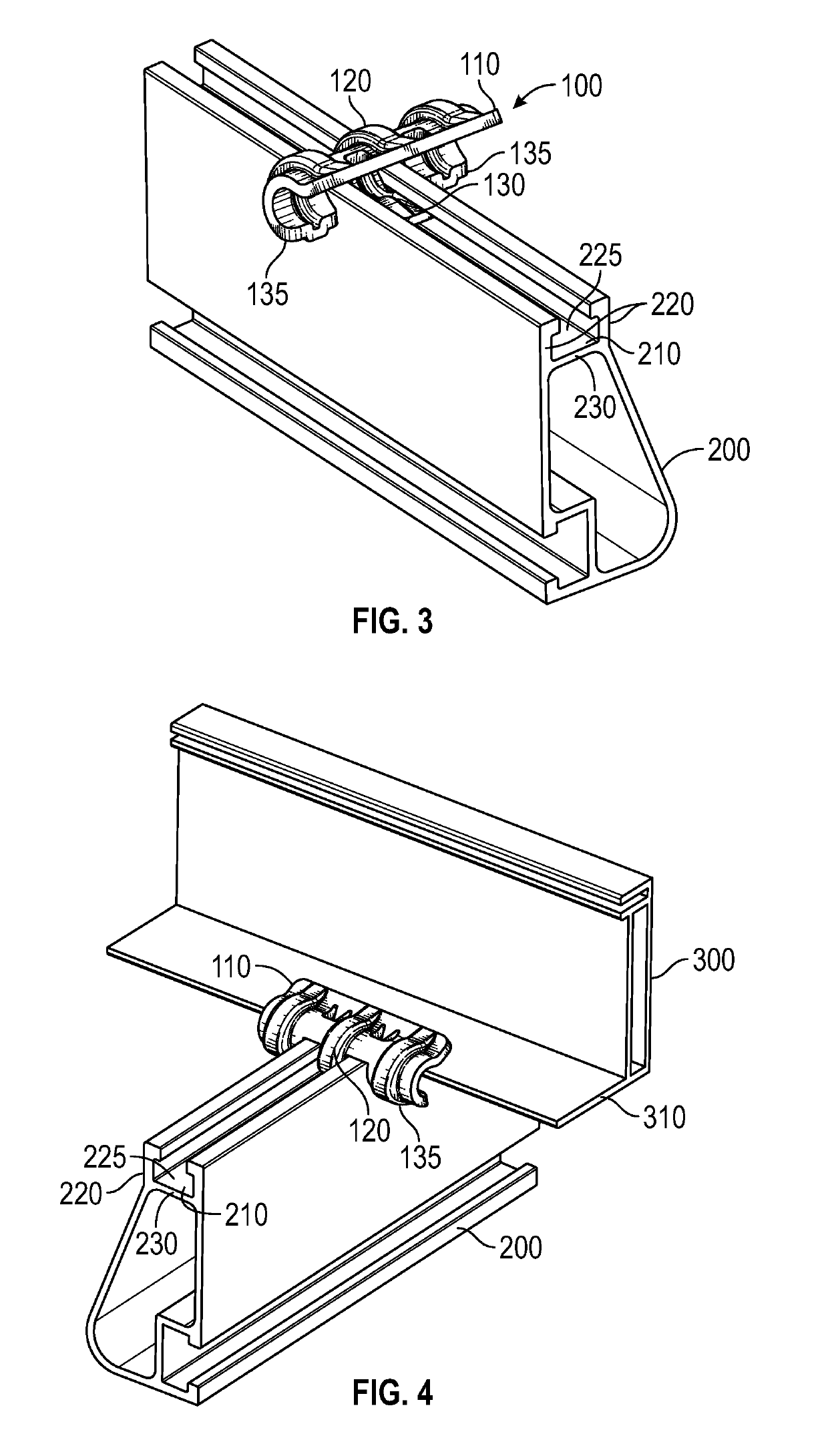
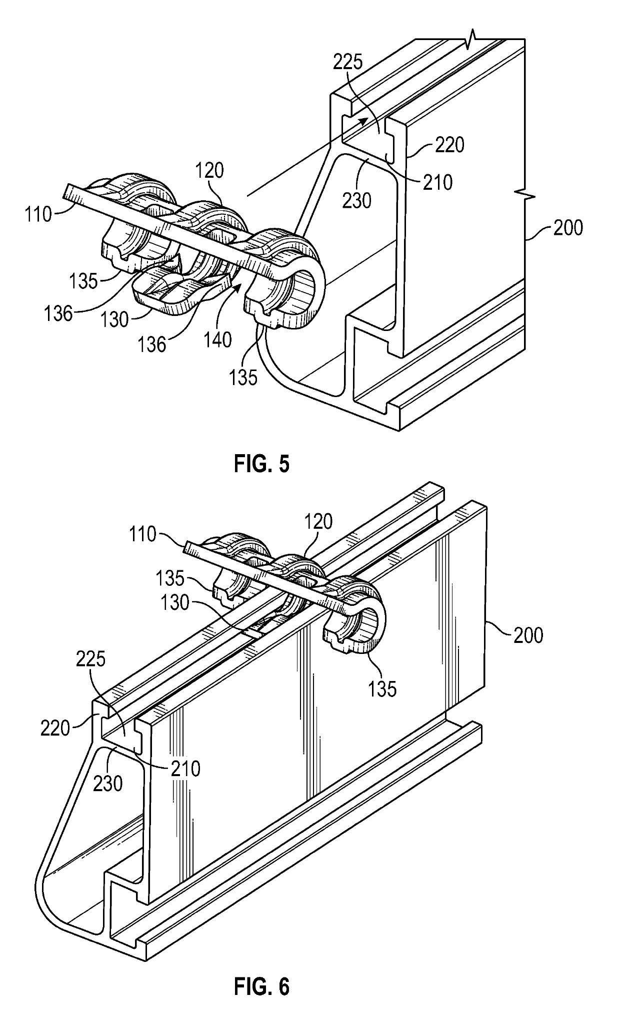
[0054]FIGS. 1 and 2 show two perspective views of an end clamp 100 for use in fastening a solar panel module ...


PUM


Abstract

In various representative aspects, an end clamp that mounts a bottom flange of a solar panel module to a rail support structure without requiring any tools for insertion while mechanically fastening and electrically bonding the solar panel module to the rail support structure. A method of installation is also provided.

Description

BACKGROUND OF INVENTIONField of the Invention[0001]The present invention relates generally to providing an apparatus for securing a solar panel module to a rail support structure. More specifically, the invention relates to the use of an end clamp that mounts a bottom flange of a solar panel module to a rail support structure without requiring any tools for installation, while also mechanically fastening and electrically bonding the solar panel module to the rail support structure.Description of the Related Art[0002]Any discussion of the prior art in the specification should in no way be considered as an admission that the prior art is widely known or forms part of common general knowledge in the field.[0003]The installation of solar panel arrays on residential roofs can be arduous and time-consuming. Depending on the array design, the components required to install the array can make the installation process even more difficult. Many of the assembly components require special tools...

Claims


Application Information

Patent Timeline
Patent Type & Authority Patents(United States)
IPC IPC(8): F24S25/634H02S20/23F24S25/636F24S25/632F24S25/30F24S25/60F24S25/00
CPCF24S25/636F24S25/30F24S25/632F24S25/634H02S20/23Y02E10/47F24S2025/801F24S2025/807Y02B10/12Y02B10/20F24S2025/6008Y02B10/10Y02E10/50
Inventor ASH, JONMEINE, SHAWN J.TAGGART, DAVID
Owner IRONRIDGE
Learn More