
Method and device for generating electrical signals corresponding to a wavelength, from polychromatic optical signals

a polychromatic optical signal and electrical signal technology, applied in multiplex communication, instruments, optical elements, etc., can solve the problem of significant optical loss detracting from quality, and achieve the effect of maximum effectiveness

Active Publication Date: 2019-03-12
ORANGE SA (FR)
View PDF9 Cites 0 Cited by
  • Summary
  • Abstract
  • Description
  • Claims
  • Application Information

AI Technical Summary

Benefits of technology

The patent describes a method for generating electrical signals from optical fibers without any need for additional optical components. The method is efficient and reduces loss by using integrated optical components. It also minimizes beam size, which avoids the need for refocus during conversion. Overall, the method improves the efficiency and reduces costs of optical fiber systems.

Problems solved by technology

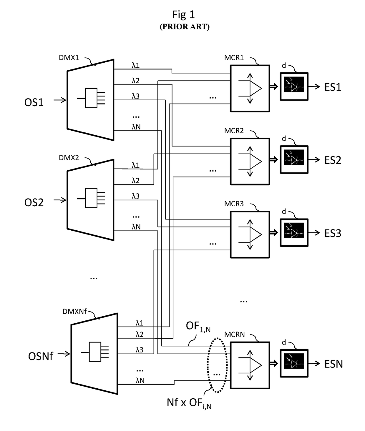
The passing of the signals through these additional optical components and these intermediate optical fibers is a significant source of optical losses detracting from the quality, even from the availability, of the service for the subscribers.

Method used


Image

  • Method and device for generating electrical signals corresponding to a wavelength, from polychromatic optical signals
  • Method and device for generating electrical signals corresponding to a wavelength, from polychromatic optical signals
  • Method and device for generating electrical signals corresponding to a wavelength, from polychromatic optical signals

Examples


first embodiment

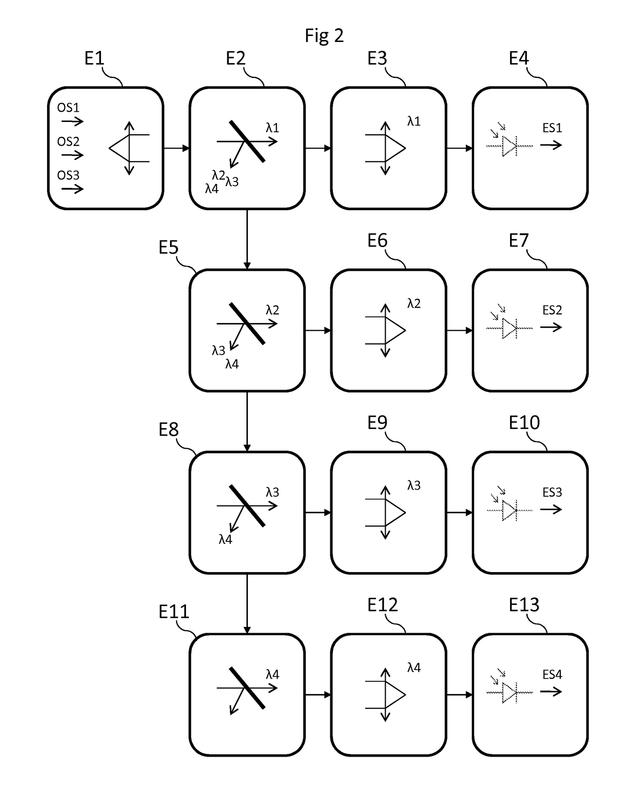
[0050]FIG. 2 presents an exemplary implementation of the method for generating a plurality of electrical signals from polychromatic optical signals extracted from a set of optical fibers, according to the invention.

[0051]In a step E1, each polychromatic optical signal OS1, OS2 and OS3 is widened to achieve a given size, for example using a collimation lens for each signal, and the duly widened optical signals are arranged and grouped together in a beam of predetermined size.

[0052]In a step E2, the beam of polychromatic signals passes through a first optical filter set to separate the light of wavelength λ1 from the rest of the light of the beam, a filter for which the size of the beam has been predetermined. This filter is, for example, a glass plate with multilayer treatment dedicated to the wavelength λ1, allowing this wavelength to pass and reflecting the others.

[0053]In a step E3, the separated monochromatic beam, consisting of the light filtered at the wavelength λ1, is focused...

second embodiment

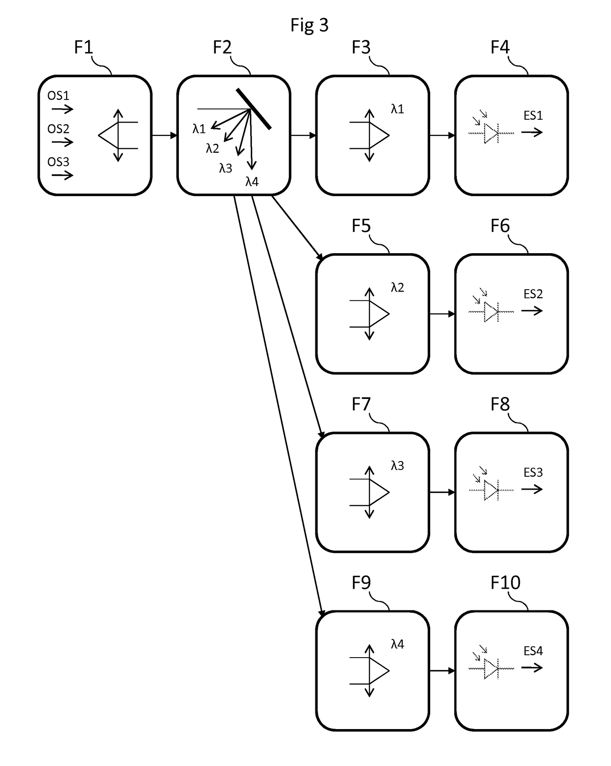
[0068]FIG. 3 presents an exemplary implementation of the method for generating a plurality of electrical signals from polychromatic optical signals extracted from a set of optical fibers, according to the invention.

[0069]In a step F1 similar to the step E1, each polychromatic optical signal OS1, OS2 and OS3 is widened to achieve a given size, for example using a collimation lens for each signal, and the duly widened optical signals are arranged and grouped together in a polychromatic beam of predetermined size.

[0070]In a step F2, the beam of polychromatic signals is reflected by an optical filter set to separate the light of each of the wavelengths λ1, λ2, λ3 and λ4 into as many beams of monochromatic optical signals, a filter for which the size of the polychromatic beam has been predetermined. This filter is, for example, a grating filter reflecting the monochromatic beams according to angles of incidence dependent on their wavelength.

[0071]In a step F3 similar to the step E3, the ...


PUM


Abstract

A method is provided for generating a plurality of electrical signals from polychromatic optical signals extracted from a set of optical fibers, a polychromatic signal including a plurality of predetermined wavelengths. An electrical signal is generated by using predetermined wavelengths. The method includes: grouping the extracted optical signals together into a polychromatic optical signal beam; separating the polychromatic signal beam into a plurality of monochromatic optical signal beams; and converting the plurality of separated monochromatic optical signal beams into the plurality of electrical signals.

Description

1. CROSS-REFERENCE TO RELATED APPLICATION[0001]This Application is a Section 371 National Stage Application of International Application No. PCT / FR2013 / 052151, filed Sep. 18, 2013, the content of which is incorporated herein by reference in its entirety, and published as WO 2014 / 044969 on Mar. 27, 2014, not in English.2. FIELD OF THE INVENTION[0002]The application for invention lies in the field of passive optical networks serving subscribers to electronic communication services, and more particularly in that of the passive optical networks with wavelength division multiplexing.3. PRIOR ART[0003]The optical distribution networks (ODN) are deployed by the electronic communication operators in order to serve all the potential clients of an area. The actual number of subscribers is very often below the potential, which gives incentive to pool several ODNs on one and the same optical interface of an optical line terminal (OLT) at the exchange, and do so in order to improve the fill rate...

Claims


Application Information

Patent Timeline
Patent Type & Authority Patents(United States)
IPC IPC(8): H04B10/67G02B6/42H04J14/02
CPCH04B10/67H04J14/0282H04J14/02G02B6/4215
Inventor CHANCLOU, PHILIPPESALIOU, FABIENNELE GUYADER, BERTRAND
Owner ORANGE SA (FR)
Learn More