
Electric motor and machine tool equipped with the electric motor

a technology of electric motors and motor parts, applied in the direction of electrical equipment, dynamo-electric machines, supports/enclosements/casings, etc., can solve the problems of inability to balance correction, and difficulty in balance correction by the balance correction component, so as to achieve easy and high-precision balance correction

Active Publication Date: 2019-03-05
FANUC LTD
View PDF35 Cites 1 Cited by
  • Summary
  • Abstract
  • Description
  • Claims
  • Application Information

AI Technical Summary

Benefits of technology

[0017]According to the present invention, it is possible to provide an electric motor enabling easy and high-precision balance correction even after operating over a long period, and a machine tool equipped with this electric motor.

Problems solved by technology

However, when coupling an electric motor to the spindle or the like of a machine tool, since the labyrinth structure will be arranged within the spindle head, balance correction has not been possible after coupling due to the above-mentioned labyrinth structure with a tap for balance correction.
For this reason, balance correction has not been possible without removing and disassembling the cooling fan, etc.
However, with such a structure, although the initial balance correction is not a problem, balance correction by the balance correction component may become difficult, from debris such as cutting oil and contamination penetrating the opening and accumulating upon being used.

Method used


Image

  • Electric motor and machine tool equipped with the electric motor
  • Electric motor and machine tool equipped with the electric motor
  • Electric motor and machine tool equipped with the electric motor

Examples


Embodiment Construction

[0029]Hereinafter, embodiments of the present invention will be explained in detail while referencing the drawings.

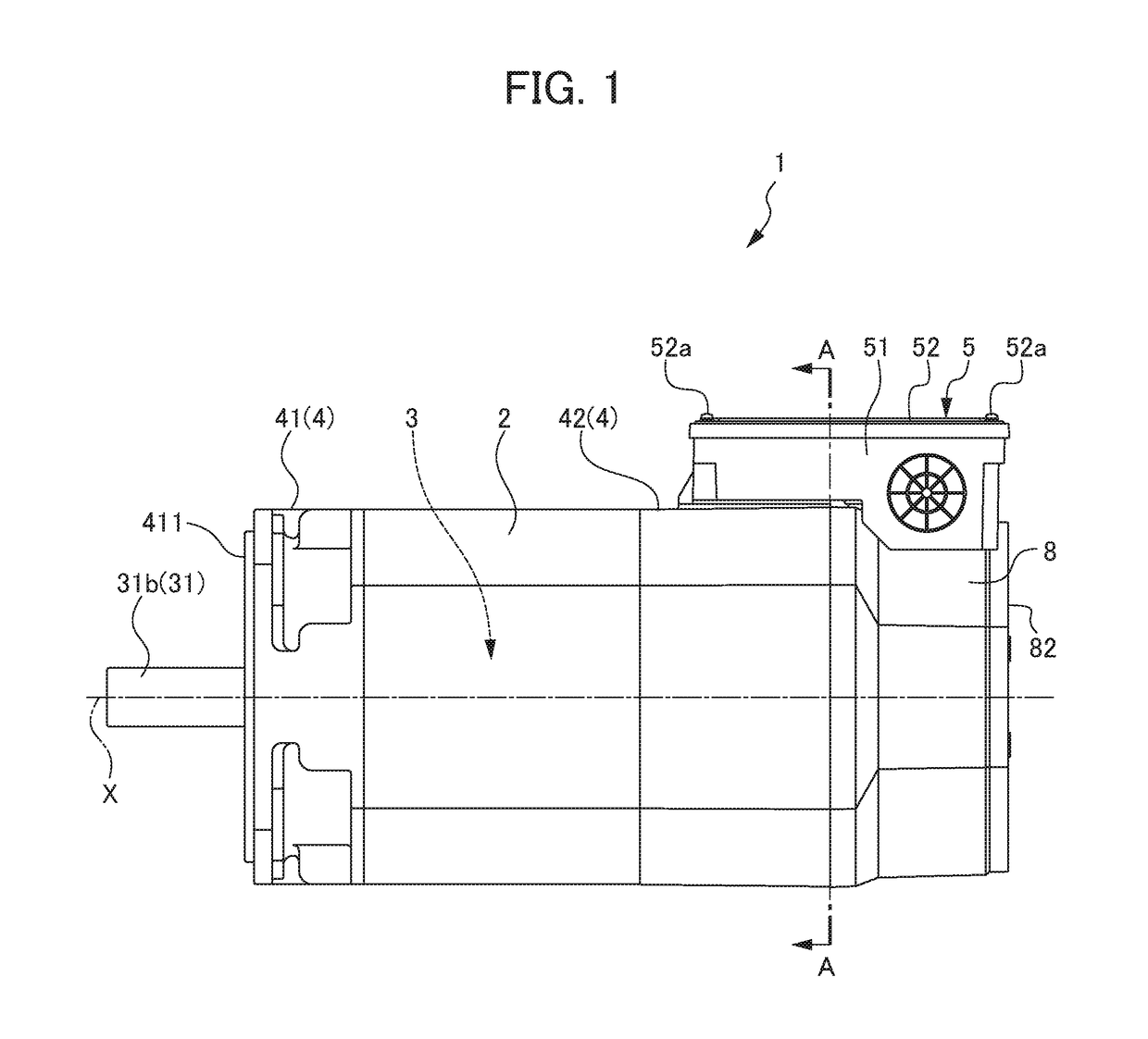
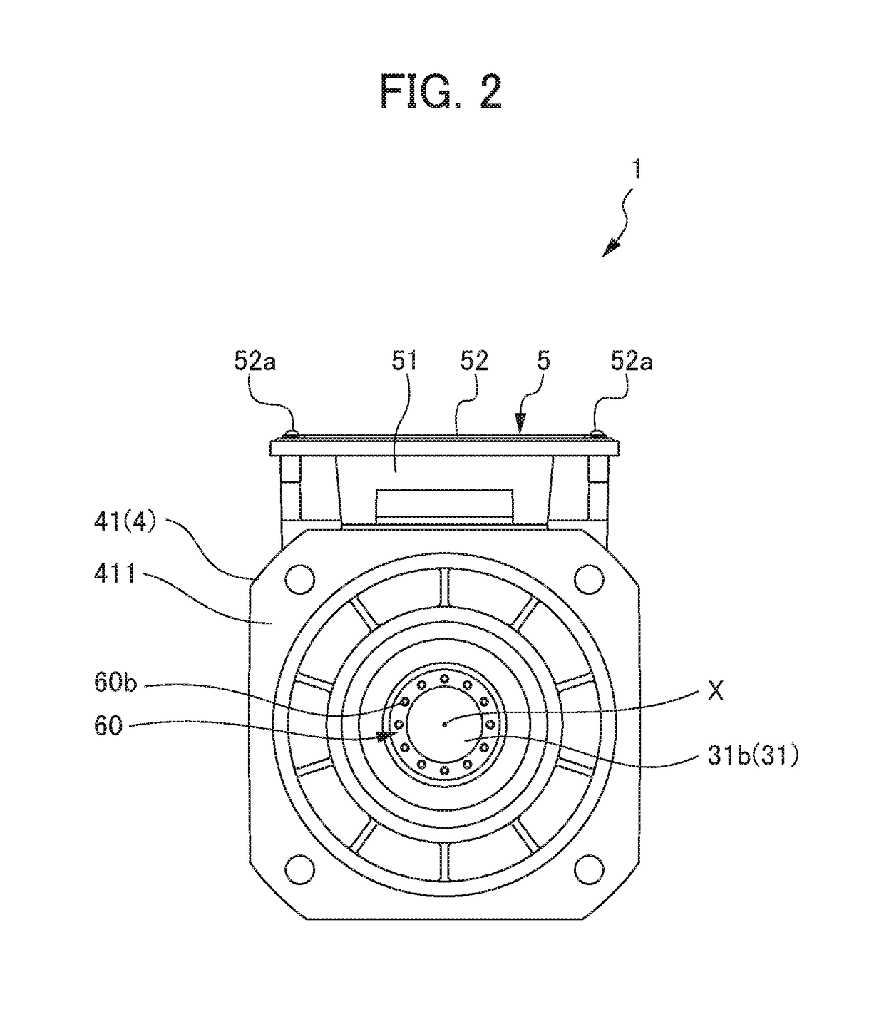
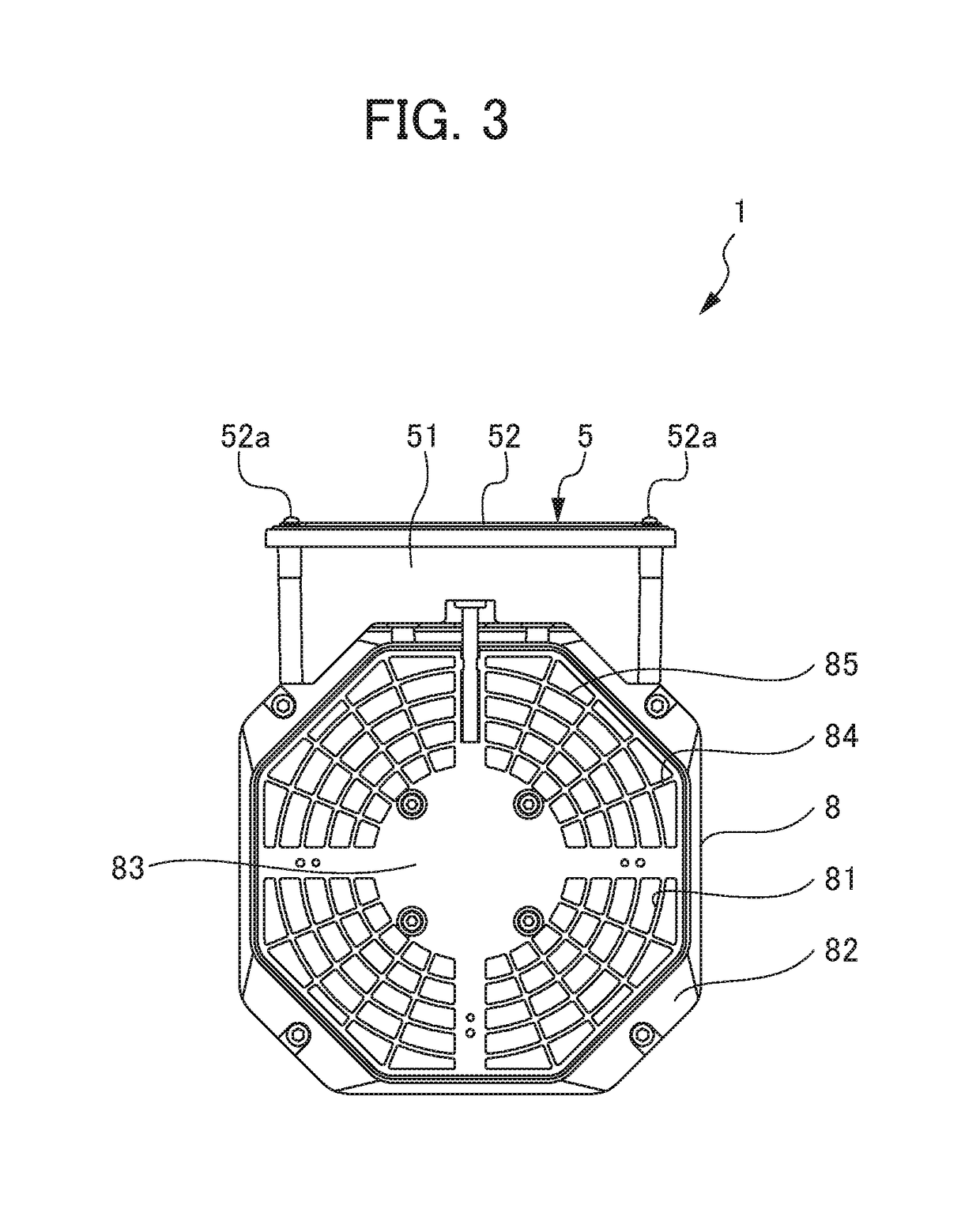
[0030]FIG. 1 is a side view of an electric motor 1 according to the present embodiment. FIG. 2 is a drawing viewing the electric motor 1 according to the present embodiment from forward in the axial direction. FIG. 3 is a drawing viewing the electric motor 1 according to the present embodiment from rearward in the axial direction. FIG. 4 is a plan view of the electric motor 1 according to the present embodiment. FIG. 5 is a partial cross-sectional view of FIG. 1; FIG. 6 is a partial cross-sectional view of FIG. 2; FIG. 7 is a cross-sectional view along the line A-A in FIG. 1; and FIG. 8 is a view showing an aspect of removing a cover member 44 in FIG. 7. In addition, FIG. 9 is a plan view of an electric motor 1A according to a modified example of the present embodiment. FIG. 10 is a partial cross-sectional side view of the electric motor 1A according to the modified exa...


PUM


Abstract

To provide an electric motor enabling easy and high-precision balance correction even after operating over a long period, and a machine toll including this electric motor. An electric motor includes: a cylindrical stator; a rotor having a rotary shaft part inserted inside of the stator; a housing installed to both ends in an axial direction of the stator; a terminal box that is mounted to the housing and accommodates a terminal block; an opening provided so as to open within the terminal box through the housing, and disposed to be separated from a ventilation passage formed in the stator; and a first balance correction component that is installed to the rotary shaft part, and corrects balance of the rotor, in which the first balance correction component is exposed within the terminal box from the opening; and a machine tool includes this electric motor.

Description

[0001]This application is based on and claims the benefit of priority from Japanese Patent Application No. 2016-125445, filed on 24 Jun. 2016, the content of which is incorporated herein by reference.BACKGROUND OF THE INVENTIONField of the Invention[0002]The present invention relates to an electric motor with a terminal box having a balance structure, and a machine tool equipped with this electric motor.Related Art[0003]In recent years, increases in the revolution speed of the spindle of machine tools has progressed, and to match this, increases in the revolution speed increase of the electric motor coupled to the spindle has also progressed. In electric motors rotating at high speed, it is necessary to balance correct the rotor with high precision so that vibrations do not become excessive during high-speed rotation. For this reason, electric motors having various balance structures have been proposed (for example, refer to Patent Documents 1 and 2).[0004]Patent Document 1: Japanes...

Claims


Application Information

Patent Timeline
Patent Type & Authority Patents(United States)
IPC IPC(8): H02K15/16H02K15/14H02K5/20H02K5/22H02K7/04
CPCH02K15/165H02K5/20H02K7/04H02K15/14H02K5/225H02K2205/09H02K5/207
Inventor NAKAZAWA, YASUYUKI
Owner FANUC LTD
Learn More