Wall washer

a technology for wall washers and washers, applied in fixed installations, light and heating equipment, semiconductor devices for light sources, etc., can solve the problem of not being able to achieve a sufficiently good light distribution by just these measures

Active Publication Date: 2019-03-05
ZUMTOBEL LIGHTING GMBH & CO KG
View PDF21 Cites 1 Cited by
  • Summary
  • Abstract
  • Description
  • Claims
  • Application Information

AI Technical Summary

Benefits of technology

[0008]The solution according to the invention presents a combination of different measures which result in a compact design of the lighting fixture or of the wall washer on the one hand, but on the other hand make it possible to achieve even, homogeneous light distribution. As the desired illuminants are LEDs, which are aligned in a row in a longitudinal direction of the lighting fixture. The light emitted by these LEDs is not directly emitted by the lighting fixture, but is deflected back by means of a concavely shaped reflector in such a way that the light output is directed towards the side and downwards. To accomplish this, the illuminants or LEDs are arranged in such a way in the upper section of the reflector that they emit light mainly in the direction that is opposite to the light emitting direction of the lighting fixture onto the reflector.
[0012]The curvature of the reflector is preferably concave, and desirably the upper section, or the section to which the illuminants are associated to, features a stronger curvature than the lower section. This ensures that even light emitted by the LEDs in relatively flat angles can still be deflected efficiently by the reflector within the above-mentioned mixing chamber and can be transmitted via the diffuser into the reflector area that is actually designated for the light output of the lighting fixture.

Problems solved by technology

Especially in the event where the dimensions of the lighting fixture are to be kept very compact, it has been discovered that it is not possible to achieve a sufficiently good light distribution by just these measures.

Method used


Image

  • Wall washer
  • Wall washer

Examples


Embodiment Construction

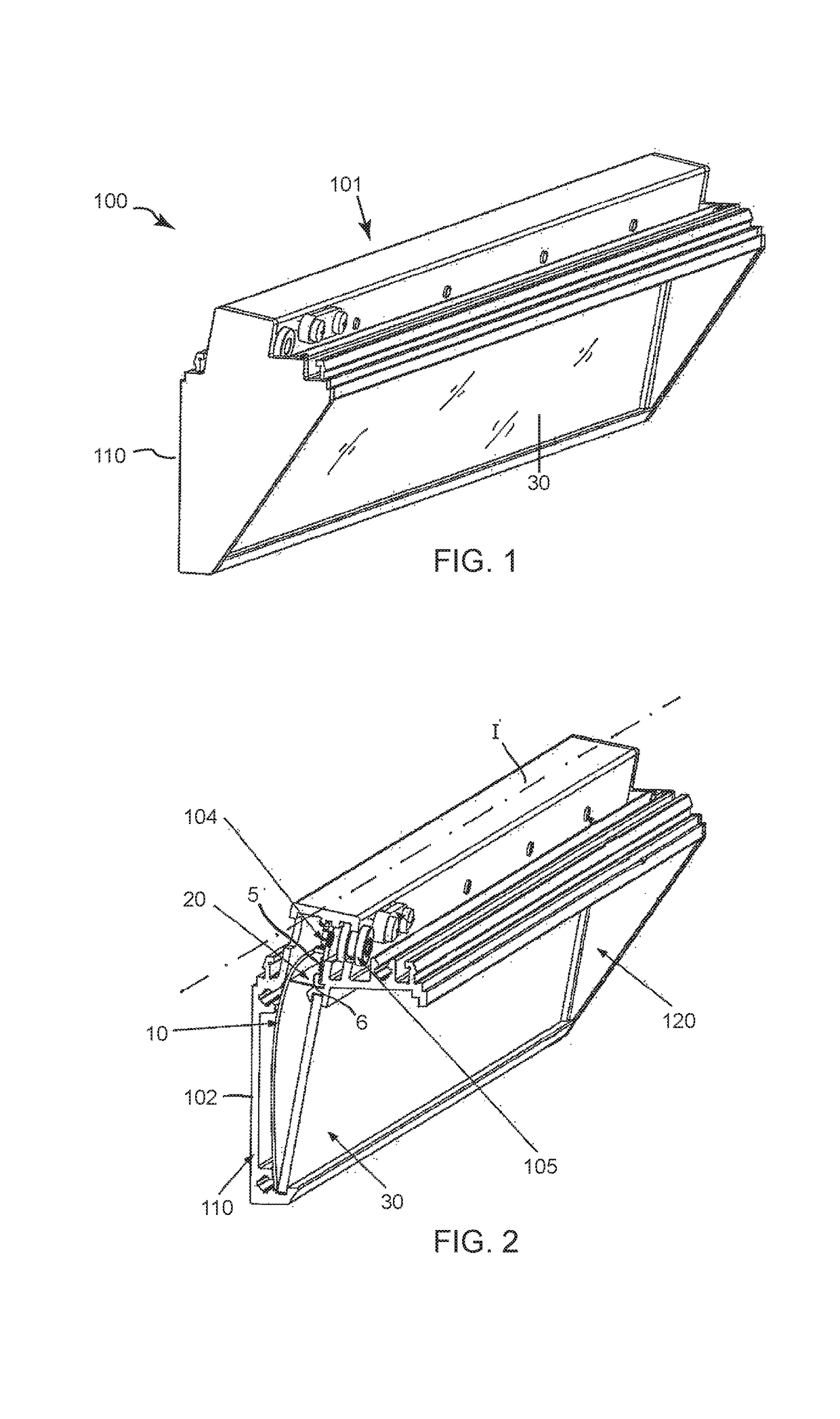
[0020]FIG. 1 illustrates an overall depiction of a lighting fixture according to the invention with the reference number 100, which is to be used as a so-called wall washer, as mentioned above. As is the case with lighting fixtures of this kind, these are attached to a horizontal mounting surface, for example to the ceiling of a room or in a comparable way. In the orientation that is intended for the operation of it, this means that the rear side (reference no. 110 in FIG. 1) of the housing 101 is essentially aligned in a vertical direction. The light of lighting fixture 100 is thereby not emitted horizontally or vertically downwards, but rather obliquely towards the side, so that in the case that the lighting fixture is arranged within the vicinity of a wall, the wall area that is located obliquely below will be illuminated. As it is generally common in the lighting technology, it is hereby intended that the so-called light field that is to be illuminated on the wall, features a br...


PUM


Abstract

In the case of a lighting fixture (100) with lighting means having LEDs (5) arranged one behind the other in the longitudinal direction (I) of the lighting fixture (100) and a reflector (10) which is concave in a plane perpendicular to the longitudinal direction (I) of the lighting fixture (100), the lighting means are arranged in the upper region (11) of the reflector (10) such that they emit light onto the reflector (10) in essentially the opposite direction from a light emission direction (A) of the light fitting (100), wherein a diffuser (20) is arranged below the lighting means and extends as far as the reflector (10).

Description

CROSS REFERENCE TO RELATED APPLICATION[0001]The present application is the U.S. national stage application of International Application PCT / EP2015 / 073864, filed Oct. 15, 2015, which international application was published on Apr. 21, 2016 as International Publication WO 2016 / 059148 A1. The International Application claims priority to German Patent Application 20 2014 104 900.2, filed Oct. 15, 2014.FIELD OF THE INVENTION[0002]The present invention relates to a lighting fixture, which is intended for the use as a so-called wall washer present invention relates to a lighting fixture, which is intended for the use as a so-called wall washer.BACKGROUND OF THE INVENTION[0003]A wall washer is understood to be a lighting fixture that is specifically designed to illuminate a vertical surface in a room, i.e. particularly it's wall. Usually, lighting fixtures that are used for this purpose are directly hung or arranged on a horizontally oriented base surface, for example, the ceiling of a room...

Claims


Application Information

Patent Timeline
Patent Type & Authority Patents(United States)
IPC IPC(8): F21V7/04F21V3/04F21S8/04F21S4/28F21V19/00F21V3/00F21V7/00F21Y103/10F21Y115/10
CPCF21V7/04F21S4/28F21S8/04F21V3/00F21V7/005F21V7/0008F21V19/003F21V3/04F21Y2115/10F21Y2103/10F21V7/09
Inventor HESSE, PETER
Owner ZUMTOBEL LIGHTING GMBH & CO KG
Why Eureka
Try Eureka