Compact linear accelerator with accelerating waveguide

a linear accelerator and waveguide technology, applied in the field of radiation therapy, can solve the problems of bulky machinery with a limited scope of volumetric angles, and the linac machine has unusable and/or unreachable angles of therapy delivery, etc., to achieve the effect of improving vacuum pumping, high vacuum, and high power of electrons and/or microwaves

Active Publication Date: 2019-02-19
RADIABEAM TECH
View PDF13 Cites 20 Cited by
  • Summary
  • Abstract
  • Description
  • Claims
  • Application Information

AI Technical Summary

Benefits of technology

[0007]The accelerating waveguide can be housed in a small volume. For example, the isolator may be disposed in a parallel configuration with the accelerating waveguide. As a further example, the magnetron may be perpendicular to the isolator and / or the accelerating waveguide. The linac may be fit into a compact housing. The compact configuration of the linac may increase clinical efficiency by allowing the device (with the assistance of a mechanical (e.g., robotic) arm) to be maneuvered with six or more degrees of freedom inside of a treatment room. The radiation device may be compact enough to treat a patient across a large range of angles in order to maximize the dose to the target treatment volume (e.g. tumor) while minimizing the dose to healthy issues by dynamically positioning the device relative to the patient. The housing of the various components of the radiation device may allow the mechanical arm to provide treatment to areas that were previously unreachable and / or tailor a dose profile to conform as much as possible to the tumor volume. The software that develops the treatment plan that specifies the angles and positions to deliver radiation from, as well as the shape of the radiation as manipulated by dynamic Multileaf collimators, can be programmed to minimize impact to healthy and / or radiation sensitive tissues. Increasing dose conformity can allow boosting the dose to the treatment volume, allowing higher probability of tumor control
[0008]Some embodiments of linac systems can minimize the size of an accelerating waveguide that is capable of achieving the energy and dose output required for radiation therapy. This may be accomplished by using multiple waveguide cells that are organized linearly. In order to reduce the size, the system may include one or more side cells for coupling RF power between the adjacent accelerating cells. In some designs, one or more cells have a side tuner configured to allow tuning of each of the one or more cells so that the waveguide can provide increased RF power and hence increased electron acceleration. In some embodiments, this tuning may be available only once shortly after manufacture of the various components of the system (e.g., parts of the waveguide).
[0010]The power of the electrons and / or microwaves that the linac generates can be high. In some embodiments, the apertures within the accelerating waveguide are small. Because the waveguide is relatively short and / or because of the size of the waveguide apertures, novel vacuum ports can be included that can provide relatively high vacuum. Two vacuum ports (e.g., one on each end of the waveguide) may be included to improve vacuum pumping.
[0011]The design of the various components of a linac head may be arranged in a way that reduces the overall size of the linac head. Accordingly, a more compact standing waveguide can be installed in the linac. The compact size and / or light weight of the linac can allow a mechanical arm to move the linac head around a patient in a treatment bed and / or within a treatment room through a range of angles comprising up to 360-degrees about a first axis defined by the intersection of the x- and y-planes as well as 360-degrees about an orthogonal axis. Previous linac machines have unusable and / or unreachable angles of therapy delivery. Moreover, the waveguide cells can be manufactured to optimize the power that is available from a combination of microwave generator (e.g., magnetron) and / or electron generator (e.g., electron gun) using specific sizes, shapes, and / or tunings.

Problems solved by technology

Modern radiation therapy techniques tend to rely on bulky machinery with a limited scope of volumetric angles at which therapy can be administered.
Previous linac machines have unusable and / or unreachable angles of therapy delivery.

Method used


Image

  • Compact linear accelerator with accelerating waveguide
  • Compact linear accelerator with accelerating waveguide
  • Compact linear accelerator with accelerating waveguide

Examples


example embodiments

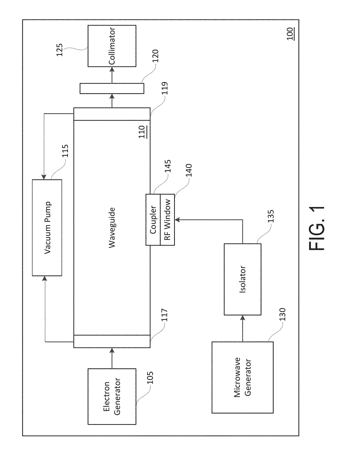
[0075]1. A linear accelerator head for use in a medical radiation therapy system, the linear accelerator head comprising:[0076]a housing;[0077]an electron generator configured to emit electrons along a beam path;[0078]a microwave generation assembly comprising:[0079]a microwave generator configured to emit microwaves in a first direction along a primary wave path; and[0080]an isolator configured to prevent microwaves from propagating in a second direction opposite the first direction along the primary wave path;[0081]a waveguide configured to contain a standing or travelling microwave, the waveguide comprising:[0082]a plurality of cells disposed adjacent one another, wherein each of the plurality of cells defines an aperture configured to receive electrons therethrough, the aperture of the plurality of cells having a diameter and defining a beam axis of the waveguide along the beam path, wherein each of the plurality of cells has a first length defined along the beam axis;[0083]one ...


PUM


Abstract

A linear accelerator head for use in a medical radiation therapy system can include a housing, an electron generator configured to emit electrons along a beam path, and a microwave generation assembly. The linear accelerator head may include a waveguide that is configured to contain a standing or travelling microwave. The waveguide can include a plurality of cells that are disposed adjacent one another, wherein each of the plurality of cells may define an aperture configured to receive electrons therethrough. The linear accelerator head can further include a converter and a primary collimator.

Description

CROSS-REFERENCE TO RELATED APPLICATIONS[0001]This application claims the benefit of U.S. Provisional Application Ser. No. 62 / 476,630, filed Mar. 24, 2017, entitled “COMPACT LINEAR ACCELERATOR WITH ACCELERATING WAVEGUIDE,” which is incorporated by reference herein in its entirety and for all purposes.BACKGROUNDField[0002]The present disclosure relates to radiation therapy, in particular to beam generation and beam hardware.Description of the Related Art[0003]Modern radiation therapy techniques tend to rely on bulky machinery with a limited scope of volumetric angles at which therapy can be administered.[0004]Systems and methods disclosed herein address various challenges related to photon therapy and photon generation.SUMMARY[0005]Described herein include embodiments related to linear accelerators (“linacs”) and related components. A linac is a device commonly used for external beam radiation treatments for patients with diseases, such as cancer. Some linear accelerators may be used ...

Claims


Application Information

Patent Timeline
Patent Type & Authority Patents(United States)
IPC IPC(8): H05H9/00H05H9/02A61N5/10G21K1/04H05H9/04
CPCH05H9/02H05H9/04G21K1/046A61N5/1045H05H9/048G21K1/02
Inventor AGUSTSSON, RONALDBERRY, ROBERTBOUCHER, SALIMEHARTZELL, JOSIAHKUTSAEV, SERGEYMCNEVIN, JACOBVERMA, AVINASH
Owner RADIABEAM TECH
Why Eureka
Try Eureka