Infrared thermometer

a thermometer and infrared technology, applied in the field of infrared thermometers, can solve the problems of difficult to measure a precise body temperature and the possibility of thermometers producing errors in the measurement of body temperature, and achieve the effect of simple structur

Active Publication Date: 2019-01-29
BIO ECHO NET
View PDF17 Cites 21 Cited by
  • Summary
  • Abstract
  • Description
  • Claims
  • Application Information

AI Technical Summary

Benefits of technology

[0012]With this configuration, it is possible to detect the tilt angle of the main body to the human body. Thus, as the infrared thermometer does not touch a skin of the human body as a subject being inspected, for example, a baby, there is no transfer in body temperature during the contactless body-temperature measurement, so that an accurate body temperature can be measured by precisely orientating the posture of the main unit to the human body.
[0014]With this configuration, the controller refers to the reference table. Thus, even though the main unit is inclined to the human body, the measured body temperature can be corrected in response to the tilt angle, and thus it is possible to measure the body temperature more accurately.
[0016]With this configuration, the electrostatic-capacity type proximity sensor is structured to have the grounding electrode and the multiple divided electrodes. Thus, such a structure has a degree of freedom for design and therefore, it is easy to incorporate the proximity sensor into the infrared thermometer.
[0020]With this configuration, when the main unit is located at the predetermined distance, it is carried out to allow the light receiving sensor to receive the return light of the projected light, which is obtained as a result of being reflected by the human body, and further calculate the body temperature of the human body at the predetermined distance based on the quantity of infrared from the infrared sensor. Thus, as the infrared thermometer, despite its simple structure, does not touch a skin of the human body as a subject being inspected, for example, a baby, there is no transfer in body temperature during the contactless body-temperature measurement, thereby allowing the body temperature to be measured precisely.
[0022]By adopting semi-circular arc-shaped lenses for the projector lens and the light receiving lens in common, the infrared sensor can be disposed between the projector lens and the light receiving lens. Therefore, the layout of the infrared sensor in the main unit is easy and accordingly, miniaturization of the main unit can be carried out.

Problems solved by technology

For this reason, it was difficult to measure a precise body temperature heretofore since measurement error occurred in the distance between the infrared and the measuring object portion frequently.
However, as the infrared thermometer described in PTL 1 is constructed so as to touch the skin of a human body, for example a baby's skin, directly, transfer of the body temperature from the baby to a casing of the infrared thermometer could produce an error in the measurement of the body temperature.

Method used


Image

  • Infrared thermometer
  • Infrared thermometer
  • Infrared thermometer

Examples


first embodiment

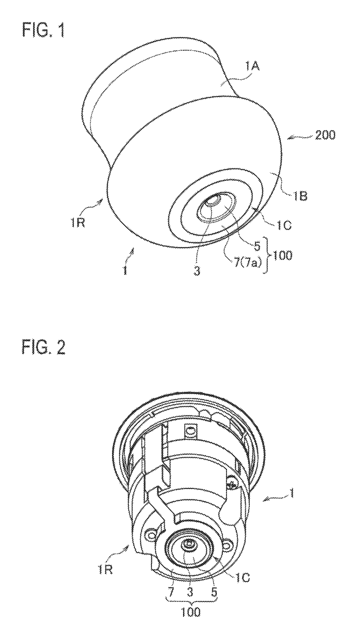
[0062]An infrared thermometer 1 according to a first embodiment will be described with reference to FIGS. 1 to 12.

[0063]As illustrated in FIG. 1, the infrared thermometer 1 according to the first embodiment includes a cover 200. The cover 200 is configured so as to be slightly-vertical barrel-shaped. Owing to this configuration, it is easy for a measurer to pinch a concave portion 1A etc. which is slightly recessed at the center of the cover 200, by fingers. Then, the measurer is supposed to pinch the concave portion 1A of the cover 200 of the infrared thermometer 1 and also measure a body temperature in no contact, at a position closer to a measuring target whose body temperature is to be measured, for example, a human skin positioned at the central part of a forehead of a human body, such as a baby's body.

[0064]Consequently, the infrared thermometer 1 is in no contact with the human skin. In other words, as the infrared thermometer does not touch a skin of a human body (e.g. baby)...

second embodiment

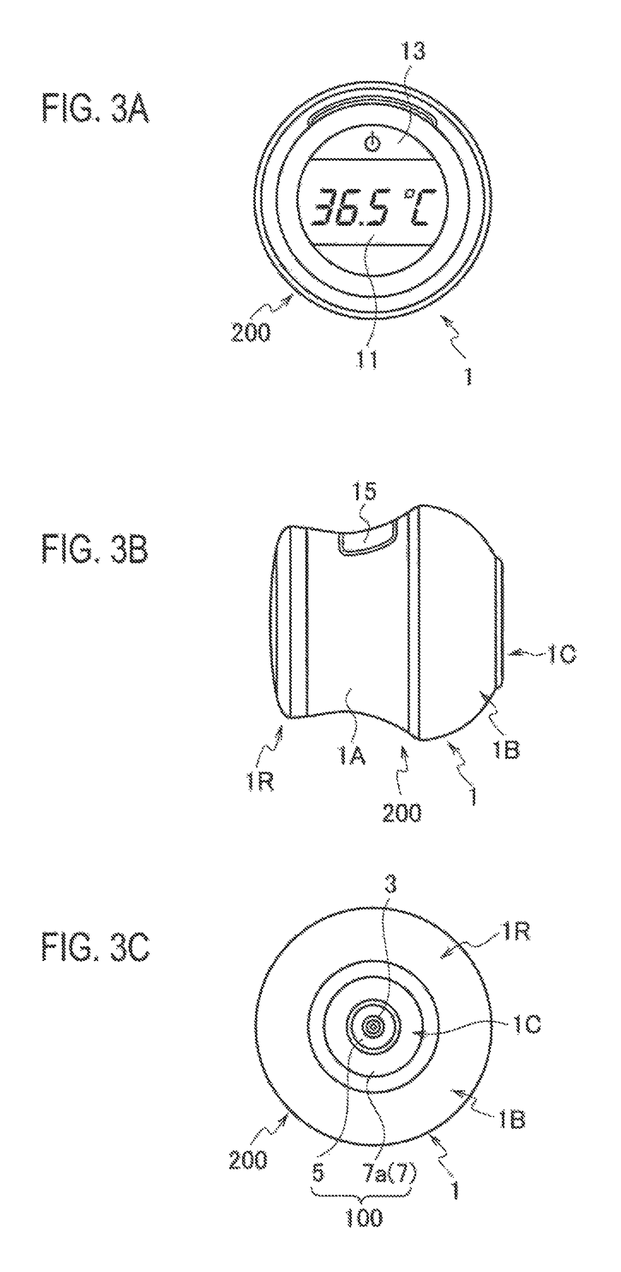
[0133]An infrared thermometer 1 according to a second embodiment will be described with reference to FIGS. 13 to 27.

[0134]As illustrated in FIG. 13, the infrared thermometer 1 according to the second embodiment includes the cover 200. The cover 200 is configured so as to be slightly-vertical barrel-shaped. Owing to this configuration, it is easy for a measurer to pinch the concave portion 1A etc. which is slightly recessed at the center of the cover 200, by fingers. Then, the measurer is supposed to pinch the concave portion 1A of the cover 200 of the infrared thermometer 1 and also measure a body temperature in no contact, at a position closer to a measuring target whose body temperature is to be measured, for example, a human skin positioned at the central part of a forehead of a human body, such as a baby's body.

[0135]Consequently, the infrared thermometer 1 is in no contact with the human skin. In other words, as the infrared thermometer does not touch a skin of a human body (e....


PUM


Abstract

An infrared thermometer for measuring a body temperature in no contact with a human body includes: a main unit incorporating an infrared sensor; a distance sensor detecting a distance between the main unit and the human body when the main unit approaches the human body; and a controller for calculating the body temperature based on quantity of infrared from the infrared sensor when the distance sensor detects that the distance between the main unit and the human body is within a predetermined distance. The distance sensor includes: a light source; a projector lens for projecting light of the light source toward the human body; a light receiving sensor; and a light receiving lens that allows the light receiving sensor to receive return light of the light, which is obtained as a result of being reflected by the human body, when the main unit is located within the predetermined distance.

Description

CROSS REFERENCE TO RELATED APPLICATIONS[0001]This application is a continuation of International Application No. PCT / JP2014 / 069746, filed Jul. 25, 2014, and based upon and claims the benefit of priority from Japanese Patent Applications No. 2013-164082, filed Aug. 7, 2013, and No. 2014-020017, filed Feb. 5, 2014, the entire contents of all of which are incorporated herein by reference.BACK GROUND[0002]Technical Field[0003]The present application relates to an infrared thermometer using an infrared sensor to measure a body temperature contactlessly.[0004]Related Art[0005]Because an infrared thermometer using an infrared sensor for measuring a body temperature is capable of measuring the body temperature quickly, the infrared thermometer is extremely effective for measurement of the body temperature of a subject, such as a baby or an infant, who tends to cry easily, sleep or move constantly.[0006]The infrared sensor is adapted so as to measure the quantity of infrared radiated from a ...

Claims


Application Information

Patent Timeline
Patent Type & Authority Patents(United States)
IPC IPC(8): A61B5/01G01J5/02G01J5/08G01D5/24A61B5/00G01J5/04G01J5/14G01J5/00
CPCA61B5/01A61B5/742G01D5/24G01J5/0025G01J5/14G01J5/0265G01J5/0275G01J5/04G01J5/0875G01J5/026
Inventor TANAKA, HIDEKI
Owner BIO ECHO NET
Why Eureka
Try Eureka