
Drain closer with disengageable drain cleaner

a technology of drain cleaner and drain pipe, which is applied in the field of drain closer, can solve the problems of inability to clean up after cleaning, etc., and achieve the effect of a larger area

Inactive Publication Date: 2019-01-22
VONG BINH GIA
View PDF9 Cites 1 Cited by
  • Summary
  • Abstract
  • Description
  • Claims
  • Application Information

AI Technical Summary

Benefits of technology

The patent text describes a plug with a passage for a flexible member to pass through. The flexible member has a gripping portion that can be compressed by the user's fingers and thumb, making it easier to insert and remove from the passage. A removable cover is also included to hold the gripping portion. The technical effect of this design is to provide a convenient and comfortable user experience when engaging with the plug.

Problems solved by technology

It is a well known and common problem with modern plumbing, which employs drains for sinks and the like, that clogs will inevitably develop in such drains over time.
Such clogging of drains is especially prevalent where the drains are connected to sinks and bathtubs and similar plumbing components.
While some such clogs result from non soluble objects being unintentionally deposited into the drain, typically a more common cause for drain clogging is a build-up of hair and other organic material that is flushed into a drain.
Such work well on clogs which are not fibrous but are not adapt at dislodging hair and the like, and such plungers do not work well when adjoining sink drains converge to a common outlet, since pressure from the plunging will generally communicate to the unclogged adjoining sink.
While some flexible member cleaning tools are deployable into a drain without removing the plug or stopper, such an endeavor is fraught with peril since the snaring flexible member can easily break the fragile plastic engagement of the drain plug distal end with the pivoting rod within the drain.
Unfortunately, such a mechanical disengagement and drain disassembly, is generally beyond the mechanical abilities of most home and business owners.
They thus employ cleaning devices at the risk of damaging the closure actuation system of the drain, or seek the help of a plumber or other drain cleaning professional at a cost in money and time to the sink owner.
Various limitations of the related art are already known or will become apparent to those skilled in the art upon a reading and understanding of the specification below and the accompanying drawings.

Method used


Image

  • Drain closer with disengageable drain cleaner
  • Drain closer with disengageable drain cleaner
  • Drain closer with disengageable drain cleaner

Examples


Embodiment Construction

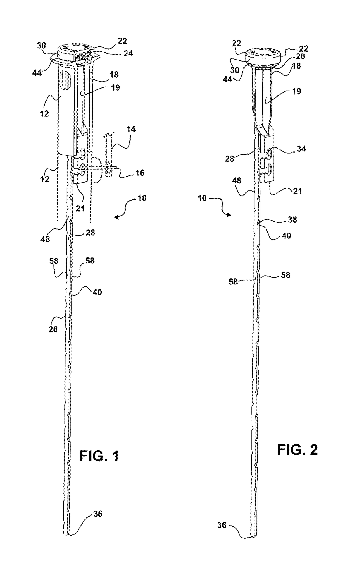
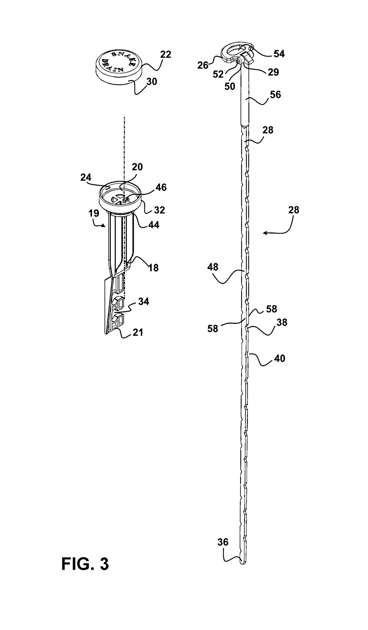
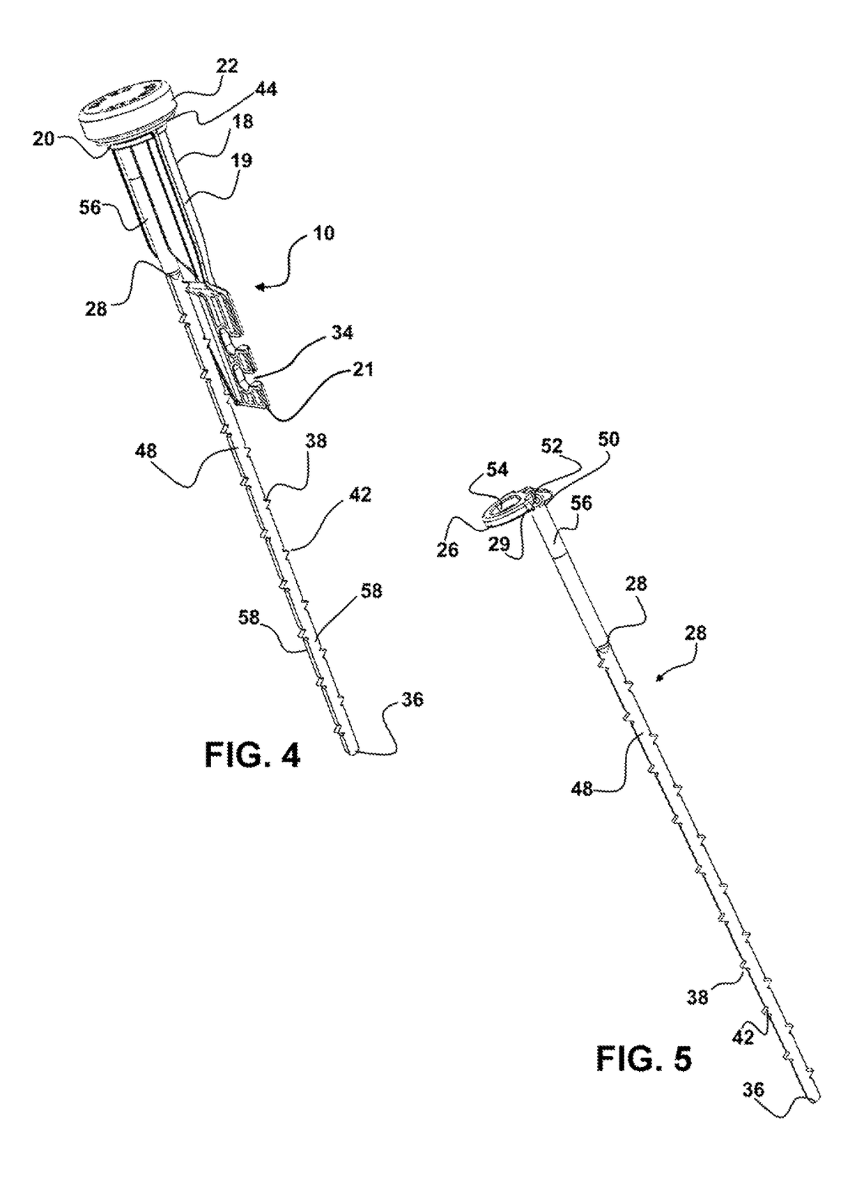
[0029]Now referring to drawings in FIGS. 1-5, wherein similar components are identified by like reference numerals, there is seen in FIG. 1, a depiction of the combination drain plug and sink cleaning device 10 herein, which is configured for operative engagement within a conventional sink or tub drain 12. FIG. 1 is shown for clarity as to such conventional sink and tub drain 12 configurations, and in no manner should be considered limiting.

[0030]Referring now to the device 10 as shown in FIGS. 1-2, a body 18 of a plug 19 of the device 10 is configured at a first end 20 for removably engagement of a cap 22 thereon. In the removable engagement of the cap 22 shown in FIGS. 1-2, the cap 22 seals a cavity 24 which is formed at a first end 20 of the body 18. This cavity 24 is sized for holding therein, a gripping portion 26 (FIG. 3) positioned at a first end of a flexible member 28.

[0031]Currently the cap 22 has a removable engagement at or adjacent the first end 20 of the body 18 which ...


PUM


Abstract

A drain closer having a body forming a plug configured for engagement in a drain or sink. The drain closure includes a flexible member translatable through a passage in the body of the plug for snagging hair or fibrous matter within the drain. The flexible member is engageable and disengageable from the plug positioned in the drain by sliding it into and out of the passage running axially through the body of the plug.

Description

FIELD OF THE INVENTION[0001]This application claims priority to U.S. Provisional Patent Application Ser. No. 62 / 601,110 filed on Mar. 11, 2017 which is incorporated herein in its entirety by this reference thereto.[0002]The disclosed device relates to drains for sinks. More particularly, it relates to a drain closer device adapted for engagement in a sink drain which includes a disengageable cleaner and de-clogging component which may be removed and reinserted into the drain to clear clogs such as those caused by hair and other elongated debris which tend to clog drains.BACKGROUND OF THE INVENTION[0003]It is a well known and common problem with modern plumbing, which employs drains for sinks and the like, that clogs will inevitably develop in such drains over time. Such clogging of drains is especially prevalent where the drains are connected to sinks and bathtubs and similar plumbing components.[0004]While some such clogs result from non soluble objects being unintentionally deposi...

Claims


Application Information

Patent Timeline
Patent Type & Authority Patents(United States)
IPC IPC(8): E03C1/23E03C1/302
CPCE03C1/302E03C1/2302E03C1/22E03C1/262
Inventor VONG, BINH GIA
Owner VONG BINH GIA
Learn More