Three dimensional imaging method of a limited zone of a patient's vasculature

a three-dimensional imaging and limited area technology, applied in the field of three-dimensional imaging methods of human vasculature, can solve the problems of difficult interpretation of difficult to build in the mind of the radiologist a clear representation, and difficulty in interpreting the actual local vessel configuration

Active Publication Date: 2018-12-25
GENERAL ELECTRIC CO
View PDF9 Cites 0 Cited by
  • Summary
  • Abstract
  • Description
  • Claims
  • Application Information

AI Technical Summary

Benefits of technology

[0011]To facilitate the analysis of the vascular architecture, embodiments of the invention propose new ways to visualize the patient's vasculature in the three dimensional image. Therefore, embodiments of the invention aim to ease the visualization of three dimensional images of patient's vasculature. Preferably, a new dimension, which is the time dimension, is brought in the representation of an image which is already a static three dimensional image. The resulting three dimensional image plus time (3D+t) information, avoids vessel superimposition and eases the visual tracking of a vascular path in the three dimensional image where many vessels may be entangled. This type of proposed representation will ease the understanding of the vascular architecture, it will ease the navigation of a tool (e.g. guidewire, catheter) within this vascular architecture and it will also ease the identification of the feeder(s) of the targeted pathology (tumor or arteriovenous malformation).
[0017]Preferably, the three dimensional imaging method is performed by an interventional imaging system. Intrinsic flexibility of interventional imaging system and flexibility of proposed three dimensional imaging method according to embodiments of the invention combine together to offer a very flexible system allowing for visualizing the zone of interest in patient's vasculature, all this zone and only this zone, so getting rid of other portions of vasculature that are not of peculiar interest but which are mixed with the zone of interest of patient's vasculature on the displayed image.
[0021]Preferably, in a second option, said three dimensional imaging of said simulated contrast agent propagation is a cinematic representation of said segmented visible vessels of said imaged limited zone, showing directly the propagation, from said second entry point, as a function of propagation time, of contrast along said segmented visible vessels of said limited zone. This cinematic representation, which is more sophisticated, allows for a clearer way to visualize the vascular paths of interest.
[0022]Preferably, said simulated cinematic contrast agent propagation can be stopped, rewinded, advanced or looped through, by user, so as to graphically represent a vascular path of at least a segmented visible vessel of said limited zone with a varying degree of complexity. This option in the imaging treatment is very useful, since it helps the radiologist to visually follow the vascular path of interest more easily and plan the insertion of a therapeutic tool accordingly.
[0025]Preferably, said contrast agent propagation is simulated by progressively filling said segmented visible vessels of said limited zone up to a geodesic distance d=v*t from said second entry point, with v a constant velocity and t the propagation time. Here, again, a very simple way of representing the contrast propagation within the vessels of the limited zone of patient's vasculature, will be considered to be sufficient for the radiologist. The very simple representation of contrast propagation within vessels is by the way rather cheap and easy to implement.

Problems solved by technology

Therefore, it may not be easy for the radiologist to build in his mind a clear representation of the vasculature architecture in this limited zone or a region of specific interest, including vessel bifurcations or an arteriovenous malformation.
However, the number of vessels in the three dimensional image and their possible superimposition in the projective images can make difficult the interpretation of the actual local vessel configuration and suggest routes that the tool cannot actually take.
The visualization of complex vascular structures in a three dimensional image is a challenging task for the interventional radiologist.
Moreover, for an arteriovenous malformation (AVM) treatment, this is even more challenging because the anatomy of such malformations is indeed a complex pattern of abnormally entangled vessels.
This is also the case, although to a lesser degree, when analyzing a tumor that has grown a new vessel system to feed itself, as such abnormal vessels are also characteristically disorderly entangled over a feeder vessel that is thus hard to identify.
However, this model of blood propagation does not improve in any way the visualization of vascular paths, so it is useless to improve patient's vasculature visualization.

Method used


Image

  • Three dimensional imaging method of a limited zone of a patient's vasculature

Examples


Embodiment Construction

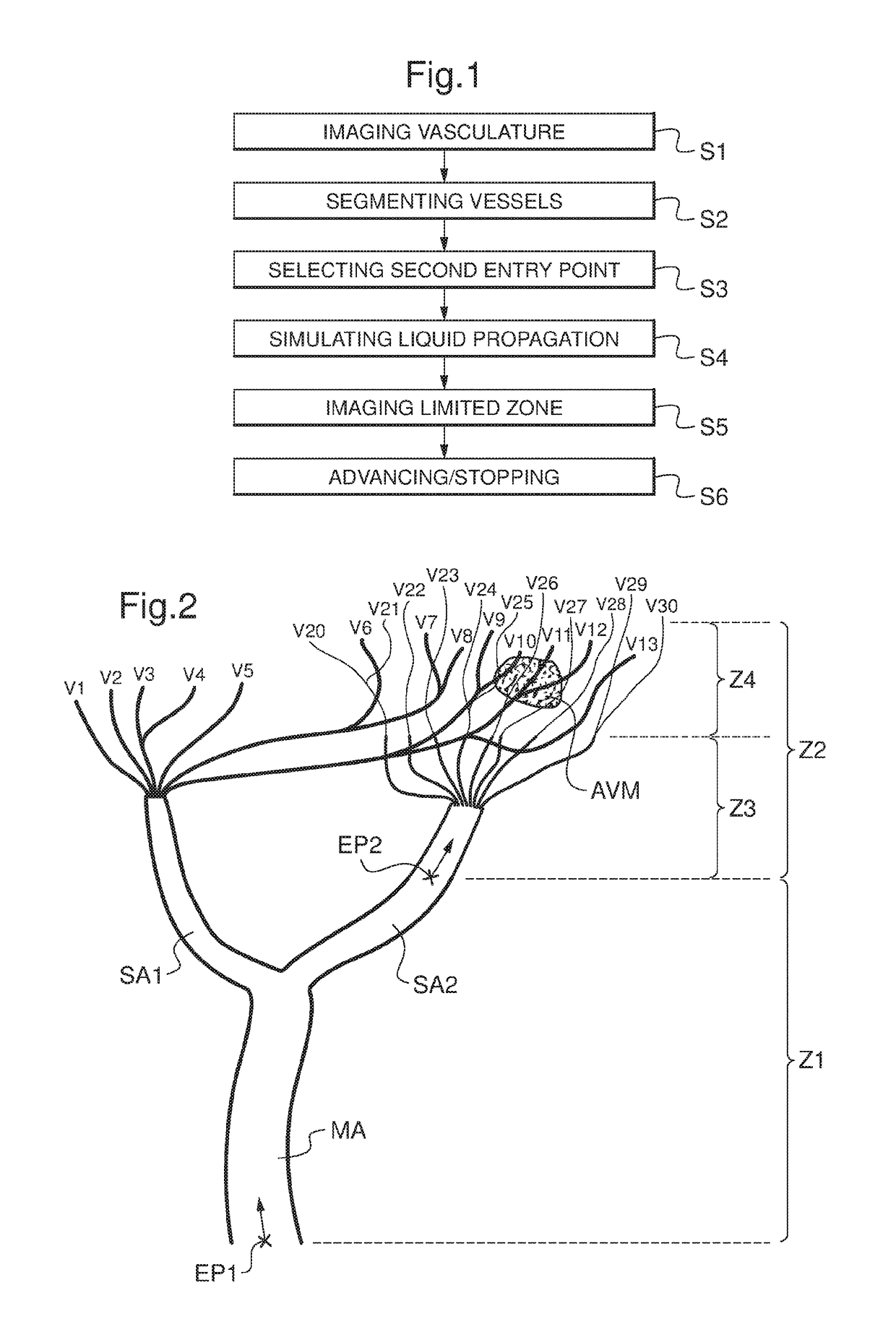
[0032]FIG. 1 shows an example of the steps of a three dimensional imaging method of a limited zone of a patient vasculature, performed according to embodiments of the invention. Successively performed steps include a step S1 of imaging vasculature, a step S2 of segmenting vessels, a step S3 of selecting a second entry point, a step S4 of simulating a contrast propagation, a step S5 of visualizing a limited zone, and a step S6 of advancing, rewinding, stopping or looping through. These steps S1 to S6 are successively performed by an interventional imaging system. Steps S1 to S6 can also be considered as functional blocks of an interventional imaging system adapted to perform those steps.

[0033]In step S1 of imaging vasculature, three dimensional imaging of real contrast agent propagation, from a first entry point, in at least part of said vasculature, is made. First entry point is preferably the entry point of the main artery. Before step S1 is performed, a contrast agent has been inj...


PUM


Abstract

This disclosure relates to a three dimensional visualization method for visualizing and / or displaying a limited zone of a patient's vasculature, the method comprising selecting an entry point within an imaged vasculature and three dimensionally visualizing a simulated contrast agent propagation from the selected entry point in a limited zone of the imaged vasculature.

Description

CROSS-REFERENCE TO RELATED APPLICATIONS[0001]This application is a US PCT National Phase filing under 35 U.S.C. 371 of copending International Application No. PCT / IB2013 / 002985, filed Dec. 31, 2013, which is incorporated herein by reference in its entirety.TECHNICAL FIELD[0002]The disclosure relates to three dimensional imaging methods of human vasculature.BACKGROUND OF THE INVENTION[0003]When imaging a patient's vasculature and when trying to isolate a limited zone of this patient's vasculature, when zooming in a limited zone of this patient's vasculature, what happens is that many vessels are entangled in this limited zone. Therefore, it may not be easy for the radiologist to build in his mind a clear representation of the vasculature architecture in this limited zone or a region of specific interest, including vessel bifurcations or an arteriovenous malformation.[0004]When performing an intervention, the radiologist navigates a tool through the network of vessels with the help of...

Claims


Application Information

Patent Timeline
Patent Type & Authority Patents(United States)
IPC IPC(8): G06K9/00A61B5/00G06F3/0484G06T7/00G06T19/00A61B6/00A61B6/03
CPCG06T7/0012A61B5/489A61B6/481A61B6/504G06F3/04842G06T19/003G06T2200/24A61B6/032A61B6/466A61B6/486A61B6/5211
Inventor TROUSSET, YVES LUCIENRIDDELL, CYRILBISMUTH, VINCENT JONAS
Owner GENERAL ELECTRIC CO
Why Eureka
Try Eureka