
Seat sliding apparatus for vehicle

a technology for sliding apparatuses and seats, which is applied to vehicle parts, movable seats, vehicle arrangements, etc., can solve the problems of increasing the operation force needed to pull the cable, etc., and achieves the effect of shortening the distance between the center of pivot and the point, increasing the height of the link mechanism, and lowering the seating comfor

Active Publication Date: 2018-12-25
TOYOTA BOSHOKU KK
View PDF11 Cites 29 Cited by
  • Summary
  • Abstract
  • Description
  • Claims
  • Application Information

AI Technical Summary

Benefits of technology

The patent text describes a problem related to the height of a link mechanism in a vehicle seat sliding apparatus. This mechanism cancels the action of a slide-lock mechanism, but its current design pivots about a pivot axis along a vertical plane, which increases the height of the link mechanism. This can make the seat uncomfortable and difficult to operate. The objective of the invention is to provide a solution that reduces the height of the link mechanism without compromising its operability.

Problems solved by technology

This may lower the seating comfort.
Further, when shortening the distance between the center of pivot and the point of application of the link mechanism in order to reduce the height of the link mechanism, the operation force needed to pull the cable increases.

Method used


Image

  • Seat sliding apparatus for vehicle
  • Seat sliding apparatus for vehicle
  • Seat sliding apparatus for vehicle

Examples


Embodiment Construction

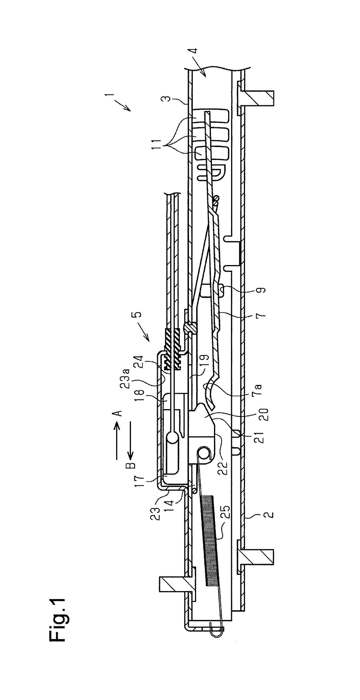
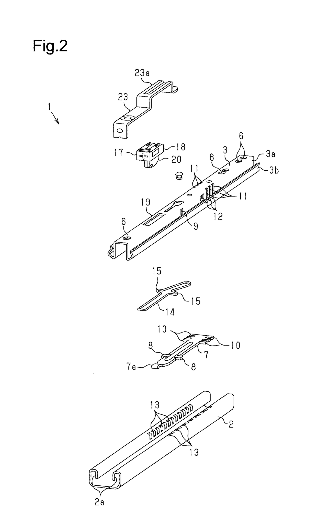
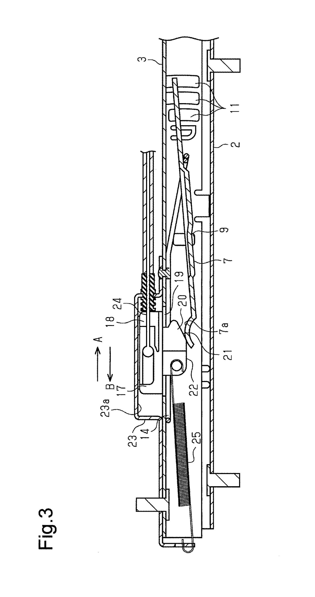
[0015]One embodiment of a vehicle seat sliding apparatus will now be described with reference to the drawings. In the seat sliding apparatus, two seat rails extend in parallel on a floor of a vehicle and support a seat cushion so that the seat cushion is slidable in a front-to-rear direction.

[0016]Two seat rails 1 each include a slide-lock mechanism 4 and a slide-lock cancellation unit 5.

[0017]More specifically, as shown in FIGS. 1 and 2, each of the seat rails 1 includes a lower rail 2 configured to be fixed to the floor, an upper rail 3 supported by the lower rail 2 in a slidable manner, the slide-lock mechanism 4, and the slide-lock cancellation unit 5.

[0018]The lower rail 2 has the form of a groove that opens upwardly at a middle portion in a widthwise direction. Guide pieces 2a downwardly extend toward opposite sides in the widthwise direction from the open portion of the lower rail 2.

[0019]The upper rail 3 is supported by the lower rail 2 so as to be slidable in a longitudinal...


PUM


Abstract

A vehicle seat sliding apparatus includes a lower rail, an upper rail, a slide-lock mechanism that pivots the lock member to a slide-lock position and holds the upper rail in a slide-lock state, and a slide-lock cancellation unit moved by operation of an operation member in a longitudinal direction of the upper rail to cancel an action of the slide-lock mechanism. The slide-lock cancellation unit includes a drive unit and an inclined surface arranged in the drive unit. The drive unit is supported by the upper rail so as to be slidable in the longitudinal direction of the upper rail. Operation of the operation member slides the drive unit. The inclined surface pivots the lock member to a slide-lock cancellation position when sliding.

Description

TECHNICAL FIELD[0001]The present invention relates to a vehicle seat sliding apparatus that supports a vehicle seat so as to be slidable in a front-to-rear direction.BACKGROUND ART[0002]A vehicle seat sliding apparatus includes a slide-lock mechanism that supports a vehicle seat on a floor to allow for sliding in a front-to-rear direction and holds the vehicle seat to restrict sliding at a desired position.[0003]One type of such a vehicle seat sliding apparatus includes an operation member, such as an operation lever arranged on a seat back, operated to actuate a lock cancellation link with a cable in order to cancel the action of the slide-lock mechanism and allow the vehicle seat to slide to the desired position.[0004]Patent document 1 discloses a walk-in device that cancels the action of a slide-lock mechanism by actuating a link with a cable.PRIOR ART DOCUMENTPatent Document[0005]Patent Document 1: Japanese Laid-Open Patent Publication No. 2010-52528SUMMARY OF THE INVENTIONProbl...

Claims


Application Information

Patent Timeline
Patent Type & Authority Patents(United States)
IPC IPC(8): B60N2/00B60N2/08B60N2/07
CPCB60N2/085B60N2/0818B60N2/0705B60N2/123
Inventor SUGIMOTO, MASAKISAKAI, MAKOTOHOSHIHARA, NAOAKIKOJIMA, YASUHIROKIMURA, SATOSHI
Owner TOYOTA BOSHOKU KK
Learn More