
Optical light guide element and a method for manufacturing

a technology of optical light guide elements and manufacturing methods, which is applied in the direction of optical waveguide light guides, instruments, applications, etc., can solve the problems of reducing the thickness of imaging devices, reducing the dimension of depth (thickness) of optical systems, and damaging optical surfaces, so as to achieve the effect of minimizing the number of polishing steps of optical surfaces

Active Publication Date: 2018-12-11
ANTERYON INT
View PDF38 Cites 0 Cited by
  • Summary
  • Abstract
  • Description
  • Claims
  • Application Information

AI Technical Summary

Benefits of technology

The present invention offers a method for manufacturing optical light guide elements with the following technical effects: minimizing optical surface polishing steps, maintaining optical dimensions without affecting optical performances, facilitating precise alignment of slanted optics, and controlling and maintaining the absolute and mutual control of position and angle between multiple small slanted surfaces. Additionally, the invention provides an effective way to redirect light impinging the light guide element in a steep angle towards the second end section, which is particularly useful in applications where the light needs to propagate in a perpendicular direction.

Problems solved by technology

Polishing steps of optical surfaces may result in damaged optical surfaces.
Although US 2012 / 0176685 teaches a demand for smaller imaging apparatuses and smaller imaging lenses mounted to the imaging apparatuses, the solution provided by this document, i.e. a refractive optical system that disposes in the optical path, a prism that refracts the optical path, thereby enabling a reduction in a dimension of depth (thickness) of the optical system, does not provide a substantial reduction of the thickness of the imaging device while maintaining high optical performances, such as wider fields of view and higher resolution.
The present inventors found that assembly and precise alignment of slanted optics at these small dimensions becomes cumbersome, slow and very expensive.

Method used


Image

  • Optical light guide element and a method for manufacturing
  • Optical light guide element and a method for manufacturing
  • Optical light guide element and a method for manufacturing

Examples


Embodiment Construction

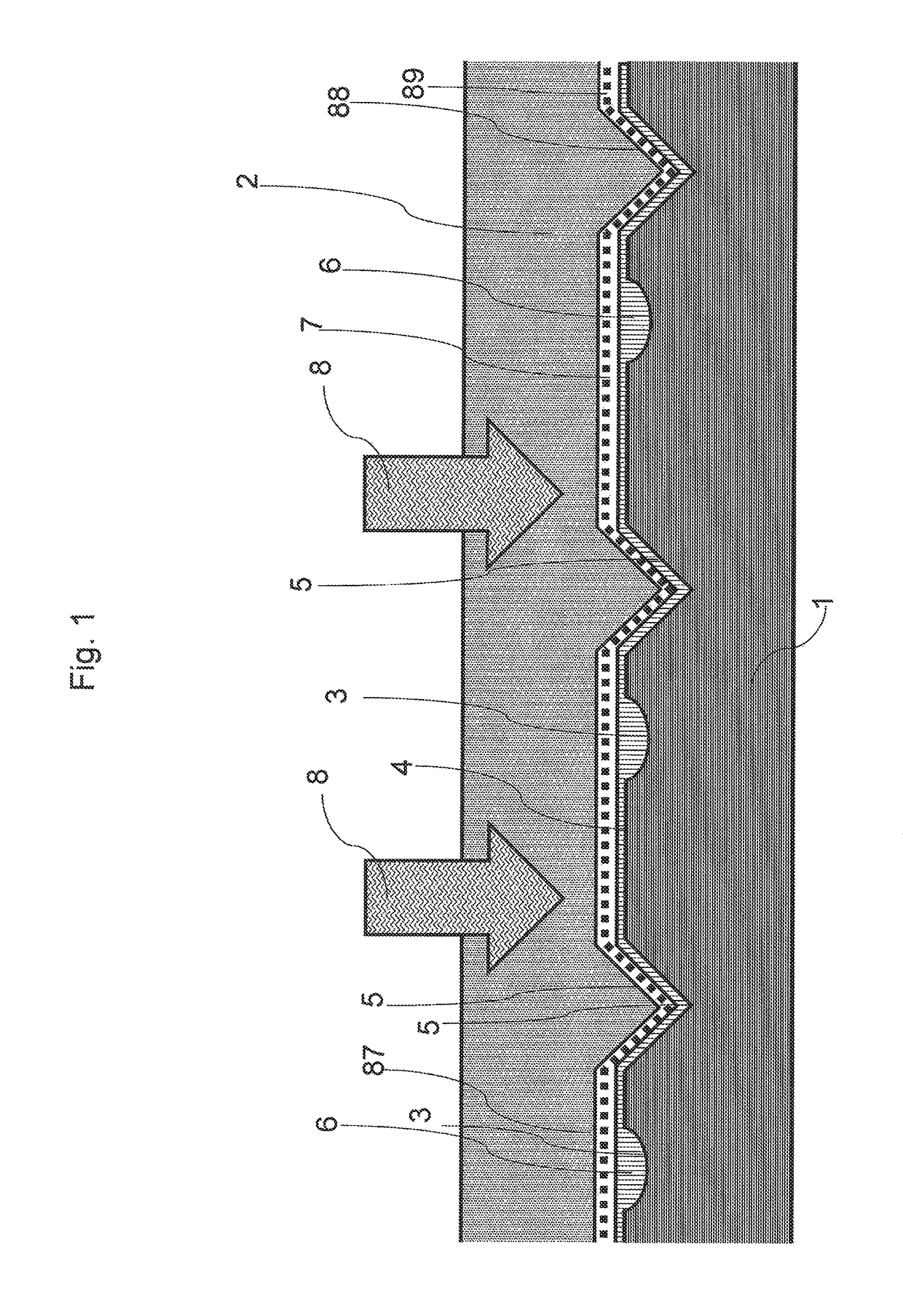
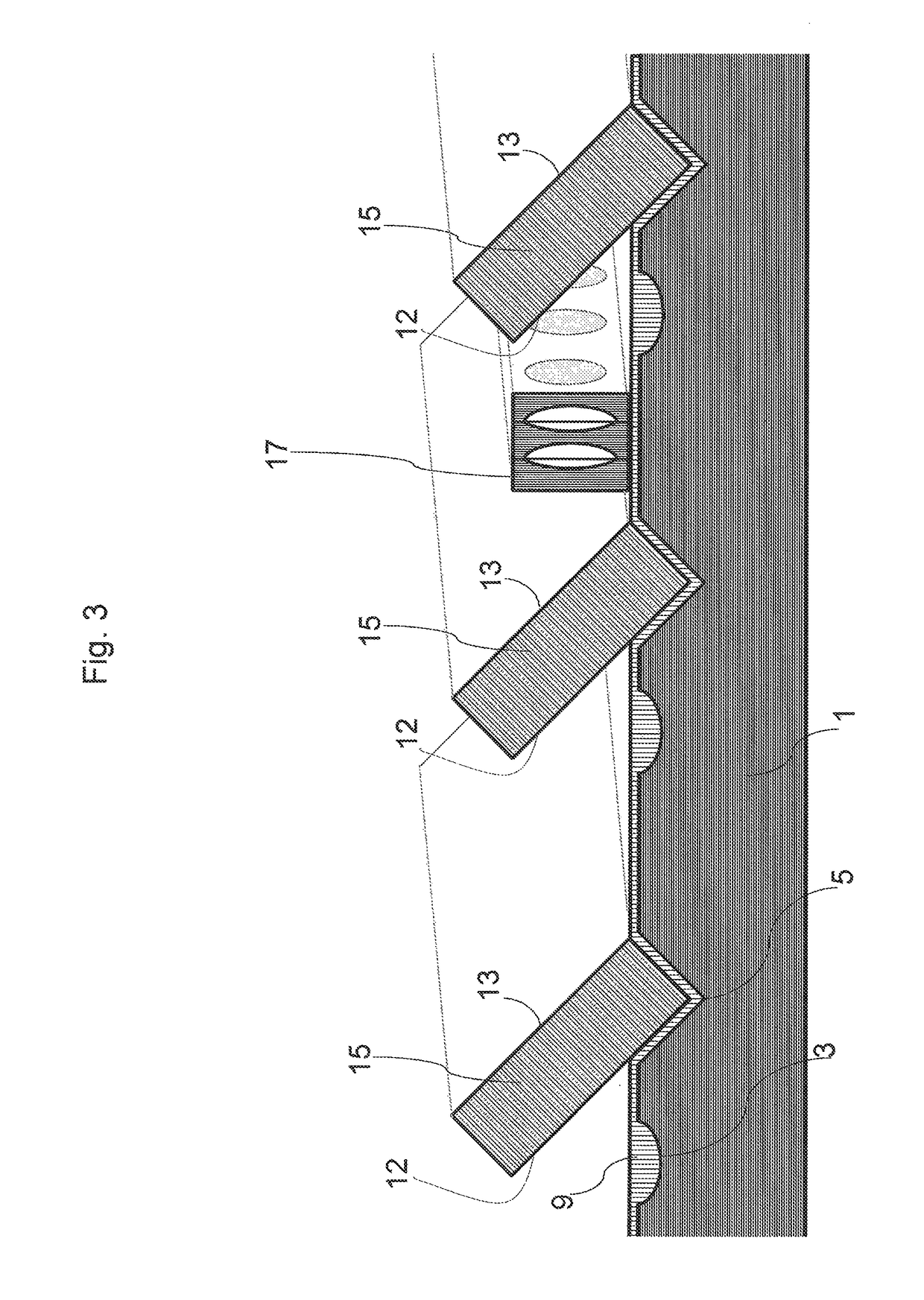
[0074]The first step of the present method for manufacturing an optical light guide element can be seen as a step of pre-fill mould with lens and positioning features. FIG. 1 shows a first mould 1 provided with a first mould surface 4 having a plurality of lens shapes 3 and recesses 5. These lens shapes can have different shapes, such as concave and convex. The mould 1 is not restricted to a specific shape of lens 3. In a first step a first liquid curable polymer 6 is applied on top of first mould surface 4 of first mould 1. In a next step a second mould 2 provided with a second mould surface 87 having a plurality of ribs 88 is brought into contact with the first mould 1. Mould 2 is transparent to light and the first liquid curable polymer 6 is cured by energy 8, for example UV curing, electron beam curing and thermal curing. The step of contacting is carried out such that the first liquid curable polymer 6 spreads into the plurality of lens shapes 3 and recesses 5 and those ribs of...


PUM

PropertyMeasurementUnit
sizesaaaaaaaaaa
diametersaaaaaaaaaa
diametersaaaaaaaaaa

Abstract

The present invention relates to an optical light guide element having a first end section with a light entrance area designed for facing a light source and having a second end section with a light exit area designed for facing a light target area, wherein the light exit area is defined by a second surface area on the optical light guide element which faces a light target area, and wherein the light entrance area is defined by a first surface area on the optical light guide element which faces the light source, wherein the first end section comprises a first inclined surface area which forms an acute angle with the first surface area of the light entrance area, wherein the second end section forms a second inclined surface area which encloses an acute angle with the surface area of the light exit area, characterized in that said first surface area on the optical light guide element which faces the light source comprises a first replicated polymer lens.

Description

CROSS-REFERENCE TO RELATED APPLICATIONS[0001]This application claims priority of Provisional Ser. No. 62 / 055,160, filed Sep. 25, 2014, Netherlands Appln. No. 2013524, filed Sep. 25, 2014 and Appln. No. PCT / NL2015 / 050664, filed Sep. 23, 2015, the disclosures of which are hereby incorporated by reference in their entirety.FIELD OF THE INVENTION[0002]The present invention relates to an optical light guide element and a method for manufacturing an optical light guide element.BACKGROUND OF THE INVENTION[0003]Such an optical light guide element is known form International application WO 2012 / 071674. This International application relates to an optical light guide element having a first end section with a light entrance area designed for facing a light source and having a second end section with a light exit area designed for facing a light target area, wherein the light entrance area is defined by a surface area on the optical light guide element which faces the light source and wherein t...

Claims


Application Information

Patent Timeline
Patent Type & Authority Patents(United States)
IPC IPC(8): G02B6/00G02B6/138G02B6/136G02B6/124G02B6/12B29D11/00
CPCG02B6/124B29D11/00692B29D11/00721G02B6/00G02B6/138G02B6/136G02B2006/12107G02B2006/12102G02B2006/12104G02B6/122
Inventor BROUWER, WILLEM MATTHIJSWOLTERINK, EDWIN MARIA
Owner ANTERYON INT
Learn More