Lamp device, LED lamp and luminaire

a technology of led lamps and lamps, applied in the field of illumination, can solve the problems of increasing the overall cost of the device, reducing production efficiency, and difficult to assemble the entire lamp device through an automatic process, and achieve the effect of improving the assembly of the lamp device and boosting productivity

Active Publication Date: 2018-11-20
SIGNIFY HLDG BV
View PDF7 Cites 0 Cited by
  • Summary
  • Abstract
  • Description
  • Claims
  • Application Information

AI Technical Summary

Benefits of technology

[0007]In view of the above, an objective of the present disclosure at least lies in providing an improved lamp device and / or luminaire, which at least can overcome one or more deficiencies existing in the prior art, thereby improving assembly of the lamp device and boosting the productivity.
[0008]According to a first aspect of the present disclosure, there is provided a lamp device, comprising: a lamp cap having a central pin for providing an electrical connection to the lamp device; and a printed circuit board at least partially located within the lamp cap, wherein a lamp driver is mounted on the printed circuit board; characterized in that a bottom edge of said printed circuit board includes a notch comprising a first contact electrically contacting said central pin. Such a notch integral to the printed circuit board obviates the need for contact welding as well as for additional connection components mounted on the printed circuit board, thereby facilitating a lamp device that can be manufactured in a straightforward and cost-effective manner.
[0012]According to a further embodiment of the present disclosure, the notch is formed as a resilient element for receiving the central pin. This ensures a particularly secure connection between the central pin and the driver circuit.
[0015]According to a further embodiment of the present disclosure, the protrusion forms part of a pattern of protrusions on said side edge that at least partially matches a thread of the lamp cap. This ensures a particularly secure fit of the printed circuit board in the lamp cap.
[0016]According to a further embodiment of the present disclosure, the notch is formed as a resilient element for receiving the central pin. This ensures a particularly secure connection between the central pin and the driver circuit.

Problems solved by technology

However, the two electrical connections usually need to be completed by manual welding, which makes it hard to assemble the entire lamp device through an automatic process, thereby reducing the production efficiency.
Although such connectors avoid the need for manual welding, they are additional components in the solid state lighting device, which makes the assembly of the device more involved and increases the overall cost of the device.
This connection has been found unsatisfactory as it is not secure enough.

Method used


Image

  • Lamp device, LED lamp and luminaire
  • Lamp device, LED lamp and luminaire
  • Lamp device, LED lamp and luminaire

Examples


first embodiment

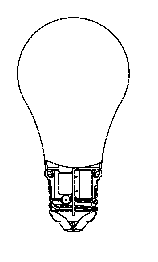
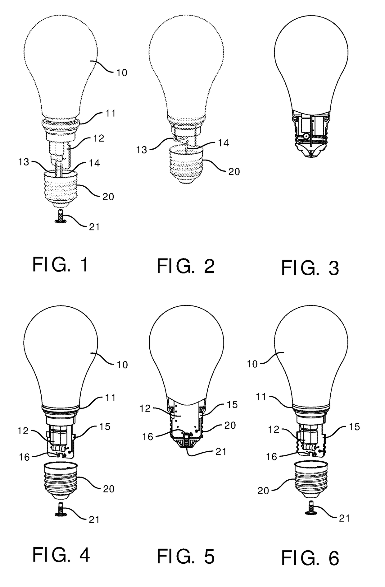
[0035]FIG. 4 schematically shows an exploded view of a lamp device 10 according to the present disclosure. The lamp device 10 comprises a lamp casing 11 and a lamp cap 20, wherein a light source (not shown) such as a light emitting diode is configured to be electrically connected to a printed circuit board within the lamp device 10, which printed circuit board is at least partially located within the lamp cap 20, which printed circuit board is at least provided with a lamp driver 12 configured to drive the light source to emit light.

[0036]According to a first embodiment of the present disclosure, alternative to the configuration of the wires 13, 14 as shown in FIG. 1 of the prior art, the lamp device 10 in FIG. 4 comprises a notch 16 on a bottom edge of the printed circuit board, to form a first contact in electrical connection to a central pin 21 of the lamp cap 20; and a second contact 15 located at a predetermined position (or height) on a side edge of the printed circuit board, ...

second embodiment

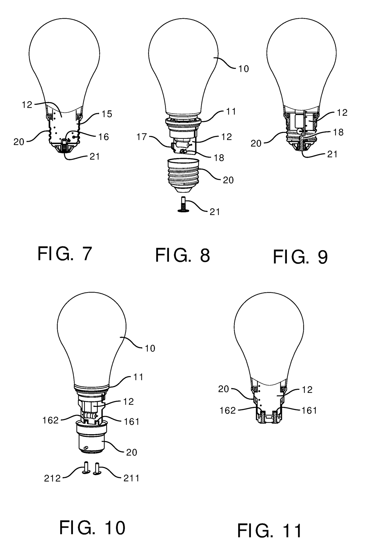
[0047]It should be appreciated that through this connection manner of the second embodiment, the electrical connection between the second contact and the lamp cap may be implemented even more securely and tightly.

[0048]FIG. 8 schematically shows an exploded view of a lamp device according to the third embodiment of the present disclosure. Similar to the structure of FIG. 4 of the first embodiment of the present disclosure, the lamp device 10 of the third embodiment of the present disclosure comprises a lamp casing 11 and a lamp cap 20, wherein a light source (not shown) in the light emitting diode LED is configured to be electrically connected on the printed circuit board within the lamp device 10; the printed circuit board is at least partially located within the lamp cap 20, and the printed circuit board is at least provided with a lamp driver 12 for driving the light source to emit light.

[0049]However, different from the first embodiment, the lamp device 10 in the third embodimen...

third embodiment

[0052]FIG. 9 schematically shows a side view of an assembled lamp device according to the present disclosure. It is seen from the side view of FIG. 9, in the assembled lamp device, the central pin 21 of the lamp cap 20 is inserted into the resilient element 18 (L pole), while a further resilient element (N pole) located at a side edge of the printed circuit board elastically abuts against the side wall of the lamp cap 20, thereby realizing electrical connection of the L pole and N pole of the lamp driver 12 to the lamp cap. Those skilled in the art should understand that the structure and location of the resilient element on the printed circuit board may be configured in any appropriate manner matching the central pin 21 and the side wall of the lamp cap 20.

[0053]Likewise, the embodiment does not need the welding of the L pole and the N pole wires in the prior art, thereby the assembly of the lamp cap may be facilitated in a simplified manner.

[0054]Through the description of the fir...


PUM


Abstract

Various embodiments of the present application provide a lamp device, an LED lamp, and a luminaire. The lamp device according to the embodiments of the present utility mode comprises: a lamp cap having a central pin (21, 211) for providing an electrical connection to the lamp device; and a printed circuit board at least partially located within the lamp cap, wherein a lamp driver (12) is mounted on the printed circuit board; characterized in that a bottom edge of said printed circuit board includes a notch (16, 161) comprising a first contact electrically contacting said central pin. The lamp device according to the present application improves the assembly of the lamp device and enhances the production efficiency.

Description

CROSS-REFERENCE TO PRIOR APPLICATIONS[0001]This application is the U.S. National Phase application under 35 U.S.C. § 371 of International Application No. PCT / IB2015 / 051893, filed on Mar. 16, 2015, which claims the benefit of Chinese Patent Application No. 201420163520.X, filed on Mar. 26, 2014. These applications are hereby incorporated by reference herein.FIELD OF THE INVENTION[0002]Embodiments of the present disclosure relate to the field of illumination, and more specifically, relate to a lamp device, an LED lamp, and a luminaire.BACKGROUND OF THE INVENTION[0003]FIGS. 1-3 show a schematic diagram of electrical connection for a lamp device in the prior art. As shown in FIG. 1, the lamp device 10 comprises a lamp casing 11 and a lamp cap 20, wherein a light source (not shown) such as a light emitting diode LED (not shown) is configured to be electrically connected to a printed circuit board in the lamp device 10, which printed circuit board is at least partially located inside the ...

Claims


Application Information

Patent Timeline
Patent Type & Authority Patents(United States)
IPC IPC(8): F21K9/238F21V23/00F21K9/235F21V23/06F21Y115/10
CPCF21K9/238F21K9/235F21V23/06F21V23/005F21Y2115/10F21V3/00F21V23/006F21K9/23
Inventor WANG, BAODUAN, XIAOQINGXIONG, YAN
Owner SIGNIFY HLDG BV
Why Eureka
Try Eureka