
Air compressor

a technology of air compressor and air storage container, which is applied in the direction of positive displacement liquid engine, pump control, pump components, etc., can solve the problems of slow inflator speed, reduced motor performance, and inability to move the piston body smoothly in the cylinder, so as to achieve the effect of significantly increasing the flow rate of compressed air entering the air storage container

Active Publication Date: 2018-11-20
CHOU
View PDF7 Cites 0 Cited by
  • Summary
  • Abstract
  • Description
  • Claims
  • Application Information

AI Technical Summary

Benefits of technology

The present invention provides an improved air compressor with an increased flow rate of compressed air into an air storage container. The cylinder of the air compressor has multiple exit holes, and these holes are designed to have different diameters. This allows for easier movement of a piston body in the cylinder, reducing resistance and allowing for smoother inflation of objects. The use of a lower-power motor can also be possible to quickly inflate objects.

Problems solved by technology

However, in conventional air compressors, there is only one exit hole defined at the cylinder for communicating with the air storage container.
However, the compressed air stored in the air storage container can exert a back force on the plug, thus restraining the plug being moved away from the exit hole.
Therefore, the piston body may not move smoothly in the cylinder, and thus the speed of inflating an object will become slow.
Furthermore, the motor of the air compressor will probably overheat and thus the performance of the motor may decrease.
Even worse, the motor may be under the risk of burning out.

Method used


Image

  • Air compressor
  • Air compressor
  • Air compressor

Examples


Embodiment Construction

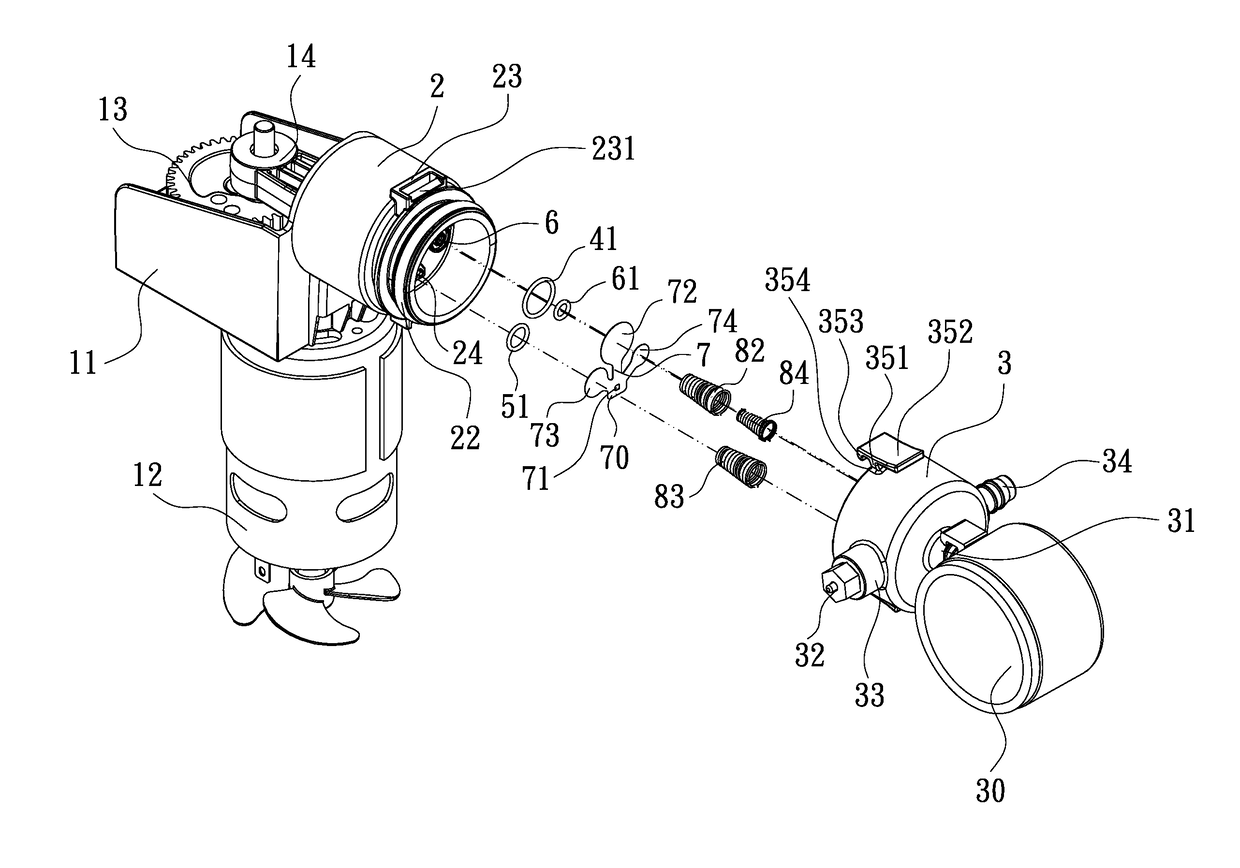
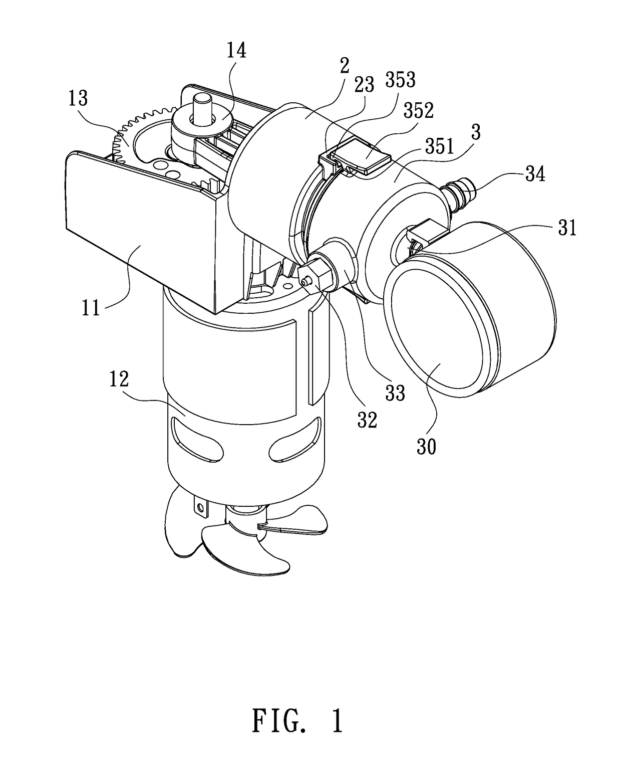
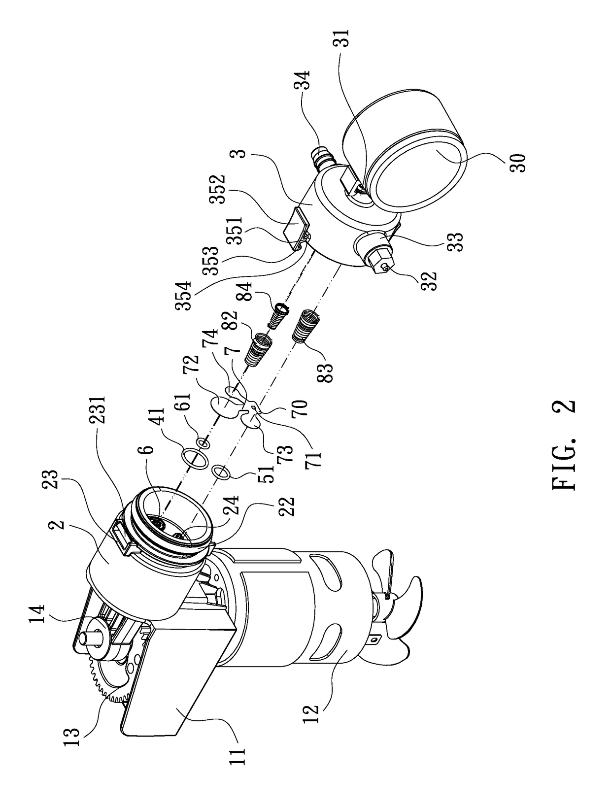
[0016]Referring to FIG. 1, an air compressor according to one embodiment of the present invention is shown, which generally comprises a main frame 11, a motor 12 mounted at the main frame 11, a cylinder 2 fitted with a piston body 14 and provided at the main frame 11, and an air storage container 3. The motor 12 can rotate a gear 13 to have the piston body 14 conduct reciprocating motion in the cylinder 2 to produce therein compressed air which is regulated to enter an inner space 36 of the air storage container 3 (see FIG. 7). The air storage container 3 is provided with one or more outlets. In this embodiment, outlets 31, 33, 34 are provided. As an example, the outlet 31 can be connected with a pressure gauge 30; the outlet 33 can be connected with a relief valve 32; the outlet 34 can be connected by a hose (not shown) to an object to be inflated.

[0017]Referring to FIGS. 2 through 5, the design of the cylinder 2 of the present invention is different from that of the cylinders of c...


PUM


Abstract

An improved motor includes a cylinder defining multiple exit holes of different diameters, which are respectively controlled by a resilient sheet having multiple branches to communicate with an air storage container. In operation, when a piston body conducts reciprocating motion in the cylinder, the compressed air produced in the cylinder can quickly enter the air storage container. The branches of the resilient sheet are subjected to different back force resulting from the compressed air in the air storage container, wherein the smallest branch of the resilient sheet is subjected to a smallest back force, so that the compressed air produced in the cylinder can enter the air storage container more easily through the smallest exit hole, so that the piston body can conduct reciprocating motion more smoothly and thus the performance of the air compressor can be increased.

Description

TECHNICAL FIELD OF THE INVENTION[0001]The present invention relates to an improved air compressor and, more particularly, to an air compressor which includes a cylinder defining a plurality of exit holes having different diameters, whereby the flow rate of compressed air entering the inner space of an air storage container can be significantly increased. Furthermore, since a branch of a resilient sheet corresponding to an exit hole having a smaller diameter will experience a smaller back force from the compressed air stored in the air storage container, so that, at a later stage of operation, the exit hole having a smaller diameter allows the compressed air to enter the air storage container more easily; therefore, the piston body can move in the cylinder more smoothly, and the efficiency of inflating an object can be increased.DESCRIPTION OF THE PRIOR ART[0002]Currently, air compressors basically has a cylinder which allows a piston body to conduct reciprocating motion therein to p...

Claims


Application Information

Patent Timeline
Patent Type & Authority Patents(United States)
IPC IPC(8): F04B49/22F04B39/10F04B39/12F04B35/04F04B39/14
CPCF04B49/22F04B35/04F04B39/14F04B39/121F04B39/125F04B39/1073F04B39/122
Inventor CHOU, WEN-SAN
Owner CHOU
Learn More