Dual purpose latch

a dual-purpose, latch technology, applied in the direction of side-by-side/stacked arrangements, electrical apparatus casings/cabinets/drawers, coupling device connections, etc., can solve the problems of unnecessarily increasing the complexity and cost of modular systems, limiting the number of arrangement options for multiple modules, and not being compatible with swiping configurations. , to achieve the effect of convenient sliding connection, robust and customizabl

Active Publication Date: 2018-11-13
CUBIC CORPORATION
View PDF12 Cites 26 Cited by
  • Summary
  • Abstract
  • Description
  • Claims
  • Application Information

AI Technical Summary

Benefits of technology

[0004]Embodiments of the present invention provide dual-purpose latches that are capable of locking modular units together in a horizontal and/or a vertical fashion using a single latch. Embodiments also provide solutions for environmentally-sealing spring connections in a swiping configuration, e...

Problems solved by technology

This unnecessarily increases the complexity and cost of modular systems and limits the number of arrangement options for multiple modules.
Such connections...

Method used


Image

  • Dual purpose latch
  • Dual purpose latch
  • Dual purpose latch

Examples


Embodiment Construction

[0037]The subject matter of embodiments of the present invention is described here with specificity to meet statutory requirements, but this description is not necessarily intended to limit the scope of the claims. The claimed subject matter may be embodied in other ways, may include different elements or steps, and may be used in conjunction with other existing or future technologies. This description should not be interpreted as implying any particular order or arrangement among or between various steps or elements except when the order of individual steps or arrangement of elements is explicitly described.

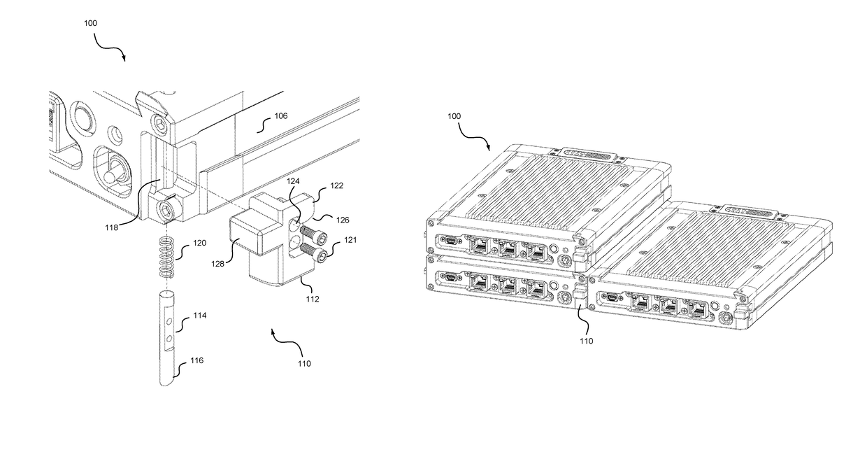
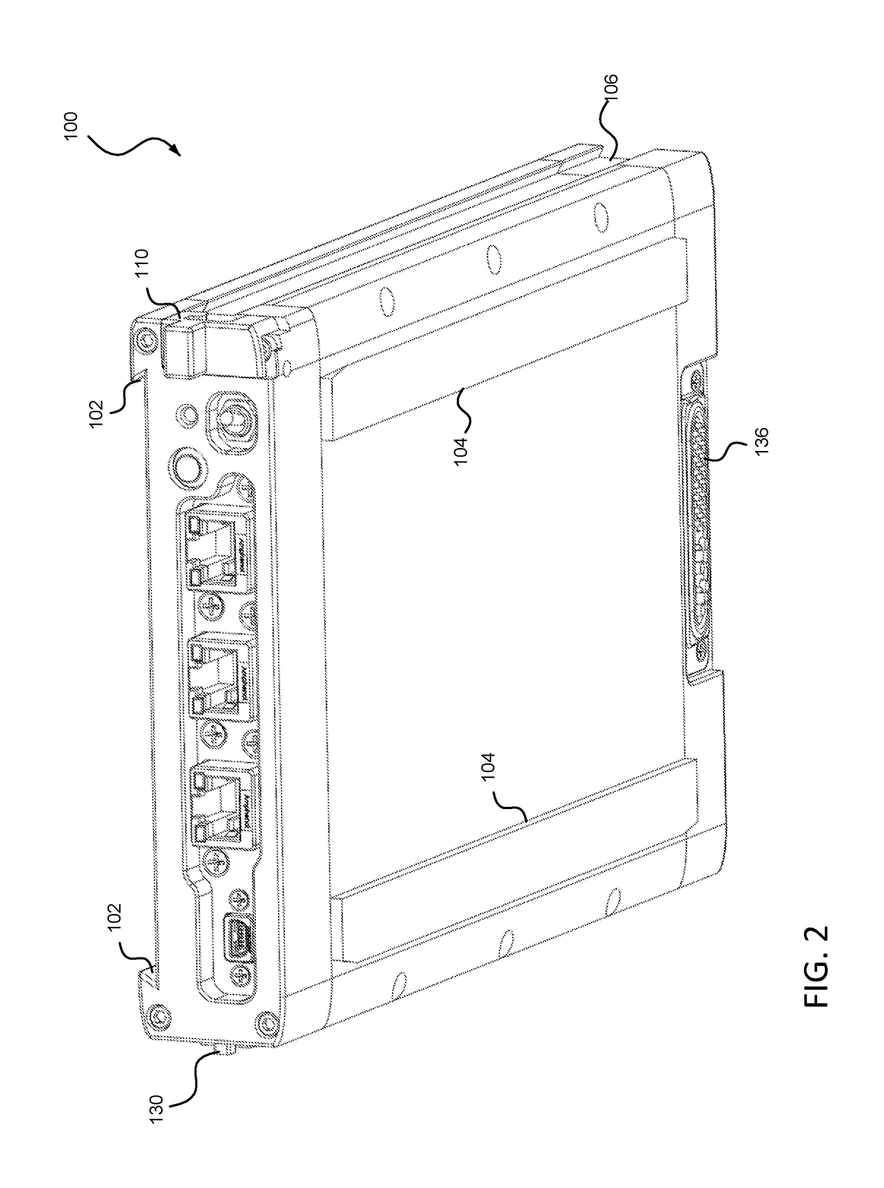
[0038]Embodiments of the invention(s) described herein are generally related to interconnectivity of electronic modules. Embodiments of the present invention provide modular electronics units that may be locked in engagement with one another using a single latch to simultaneously couple modules in a vertical stack arrangement or a side-by-side arrangement. This provides the abil...


PUM


Abstract

An electronics module includes a housing having four sides and defining an axis extending from a front to rear of the housing. Each side defines a mating feature that engages a mating feature of another electronics module. One side defines a pin-receiving receptacle, another defines a recess extending partially through a width or a thickness of the housing; and another includes a catch mechanism. A latch is mounted within the recess and includes a body having top, bottom, front, rear, inner side, and outer side surfaces. The bottom or top surface defines an opening to a vertical channel formed in the body. A hook extends from the rear surface and secures a catch on the other module. A spring-biased pin is received within the channel and mounted within the recess such that an end of the pin extends through the opening beyond a surface of the electronics housing.

Description

CROSS-REFERENCES TO RELATED APPLICATIONS[0001]This application claims the benefit of U.S. Provisional Application No. 62 / 503,847, entitled “DUAL PURPOSE LATCH”, filed on May 9, 2017, and U.S. Provisional Application No. 62 / 503,973, entitled “ENVIRONMENTALLY SEALED SWIPING SPRING PIN CONNECTOR”, filed on May 10, 2017, the entire contents of which are hereby incorporated by reference.BACKGROUND OF THE INVENTION[0002]Conventional electronics modules may be stacked or arranged in a side-by-side fashion. However, to secure multiple modules in the various configurations with movement of the modules relative to one another being constrained in three dimensions, multiple latch or other securement mechanisms are needed. For example, one type of connector may be used to secure the modules in a vertical arrangement, while separate connector may be necessary to secure modules in a horizontal arraignment. This unnecessarily increases the complexity and cost of modular systems and limits the numb...

Claims


Application Information

Patent Timeline
IPC IPC(8): H05K7/14H05K5/00H05K7/02H01R13/629H01R13/627
CPCH01R13/6275H01R13/629H05K7/1401H05K7/023H05K5/0021H01R13/17H01R13/52H05K5/0221H05K5/0247
Inventor CASTO, PAUL
Owner CUBIC CORPORATION
Why Eureka
Try Eureka