
Magnetic resonance apparatus and method for simultaneous multi-slice imaging with arbitrary slice numbers

a multi-slice, magnetic resonance technology, applied in the field of magnetic resonance imaging, can solve the problems of inability to conduct examination with conventional sms imaging with an even acceleration factor, the inability to meet the aforementioned limitations, and the inability to achieve the same acceleration factor

Inactive Publication Date: 2018-11-13
SIEMENS HEALTHCARE GMBH
View PDF3 Cites 1 Cited by
  • Summary
  • Abstract
  • Description
  • Claims
  • Application Information

AI Technical Summary

Benefits of technology

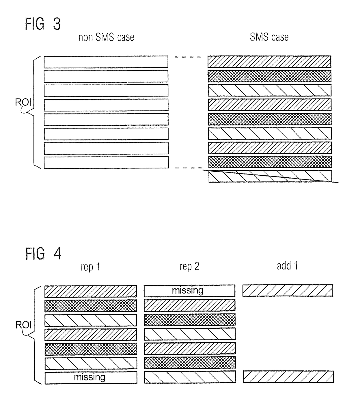
[0009]It is an object of the present invention to provide a magnetic resonance imaging apparatus and method that avoid the aforementioned limitations associated with conventional SMS imaging, and allow SMS imaging still to be used with an arbitrary number of slices in a volume to be scanned.

Problems solved by technology

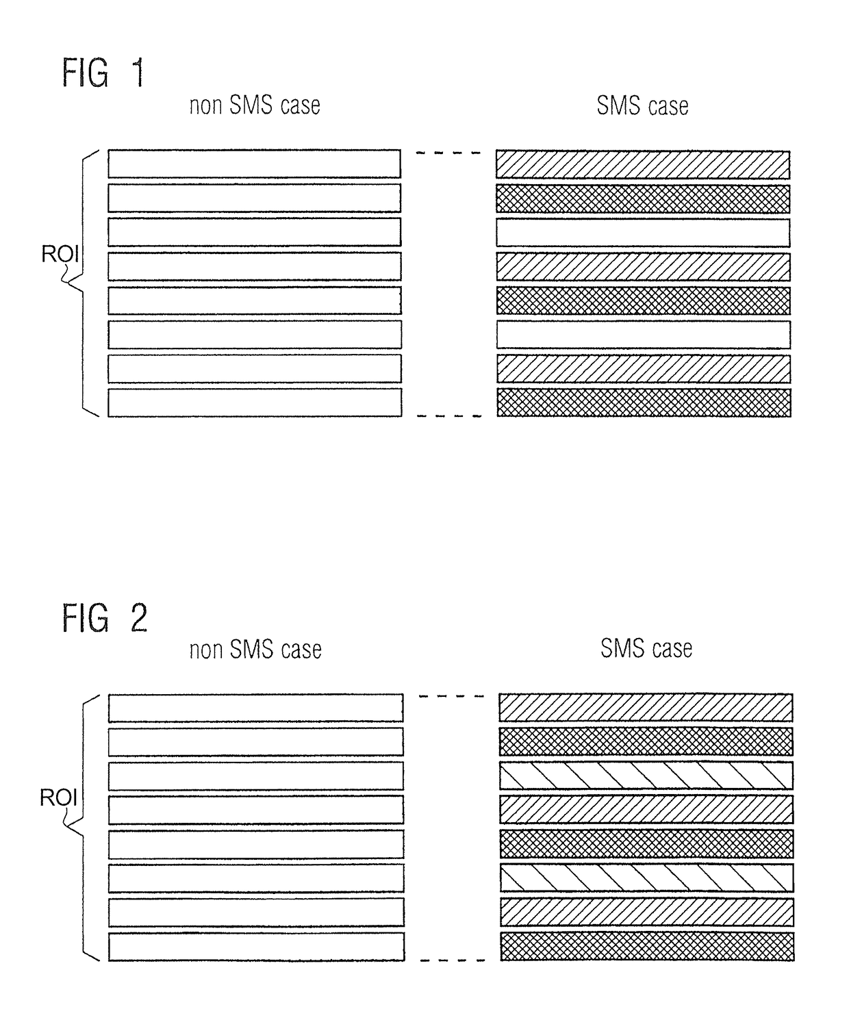
This limitation leads to the situation that, for example, an SMS-factor of two allows only even numbers of slices to be scanned, and an SMS-factor of five, for example, only allows 5, 10, 15, 20 . . . slices to be scanned.
Such is the case, for example, in neuro-imaging, wherein the slice numbers are often odd, and hence are not compatible with even SMS-factors.
It may possibly be odd or even and, if the adapted number of slices turns out to be odd, conventional SMS imaging with an even acceleration factor is then not available for conducting the examination.
Heretofore, it has been accepted as a technical limitation of SMS imaging that the selection of the number of slices will be subject to the aforementioned limitations.
In addition to then making SMS imaging unavailable for certain examinations, this also leads to the inconvenience that images acquired by SMS imaging cannot always match the slice numbers and positions of images acquired by non-SMS imaging.

Method used


Image

  • Magnetic resonance apparatus and method for simultaneous multi-slice imaging with arbitrary slice numbers
  • Magnetic resonance apparatus and method for simultaneous multi-slice imaging with arbitrary slice numbers
  • Magnetic resonance apparatus and method for simultaneous multi-slice imaging with arbitrary slice numbers

Examples


Embodiment Construction

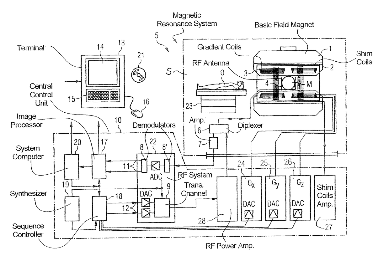
[0022]FIG. 5 schematically illustrates a magnetic resonance apparatus 5 (a magnetic resonance imaging or tomography device). A basic field magnet 1 generates, a temporally constant strong magnetic field for the polarization or alignment of the nuclear spin in a region of an examination subject O, such as a portion of a human body that is to be examined, lying on a table 23 in order to be moved into the magnetic resonance apparatus 5. The high degree of homogeneity in the basic magnetic field necessary for the magnetic resonance measurement (data acquisition) is defined in a typically sphere-shaped measurement volume M, in which the portion of the human body that is to be examined is placed. In order to support the homogeneity requirements temporally constant effects are eliminated by shim-plates made of ferromagnetic materials are placed at appropriate positions. Temporally variable effects are eliminated by shim-coils 2 and an appropriate control unit 27 for the shim-coils 2.

[0023]...


PUM


Abstract

In a method and apparatus for acquiring magnetic resonance (MR) data from a subject, wherein the MR data are acquired in respective data sets individually from multiple slices in a stack within the examination subject, and wherein the number of slices in the stack is not an integer multiple of a number of slices that are desired to be scanned simultaneously, a quotient of the number of slices in the stack and the number of slices to be acquired simultaneously is formed. A protocol for operating the scanner of the apparatus is then determined wherein the number of simultaneously scanned slices is set either by rounding by quotient up to the next highest integer, or rounding the quotient down to the next lowest integer.

Description

BACKGROUND OF THE INVENTION[0001]Field of the Invention[0002]The present invention concerns magnetic resonance imaging, and in particular concerns magnetic resonance imaging techniques for multi-slice imaging.[0003]Description of the Prior Art[0004]Many magnetic resonance imaging (MRI) examinations that are currently conducted incorporate two-dimensional (2D) measurements. In such conventional measurements, magnetic resonance data are acquired from a stack of parallel, adjacent 2D slices, with the stack covering the entirety of the region of interest in the body of the patient. Usually, nuclear spins in each slice are excited separately, i.e., the excitation takes place slice-by-slice, and the resulting magnetic resonance signals are subsequently also acquired separately (slice-by-slice). This means that the data acquisition for one slice is independent of the data acquisition from the other slices in the stack. Therefore, the number of slices in the stack can be selected without li...

Claims


Application Information

Patent Timeline
Patent Type & Authority Patents(United States)
IPC IPC(8): G01V3/00G01R33/561G01R33/483
CPCG01R33/5611G01R33/4835
Inventor BECK, THOMASBHAT, HIMANSHUHOELSCHER, UVOZELLER, MARIO
Owner SIEMENS HEALTHCARE GMBH
Learn More