Closure with lid and removable membrane
a technology of lid and membrane, applied in the field of lids for a system, can solve the problems that users may have difficulty in grasping the pull tab or the ring inside the spou
- Summary
- Abstract
- Description
- Claims
- Application Information
AI Technical Summary
Benefits of technology
Problems solved by technology
Method used
Image
Examples
first embodiment
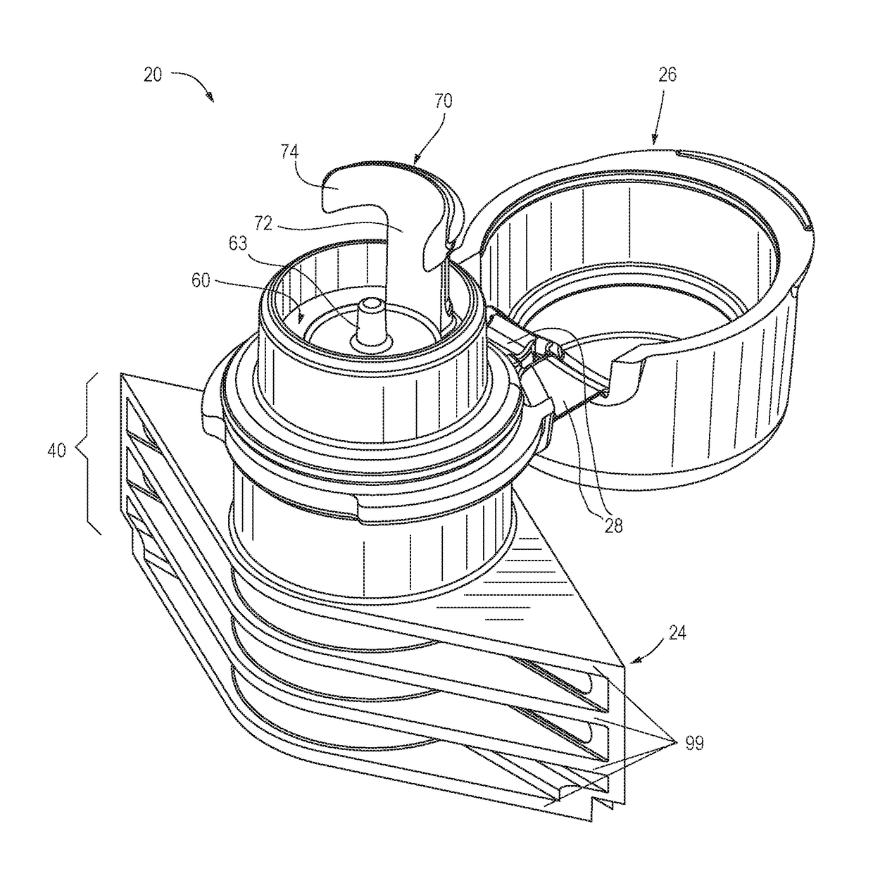
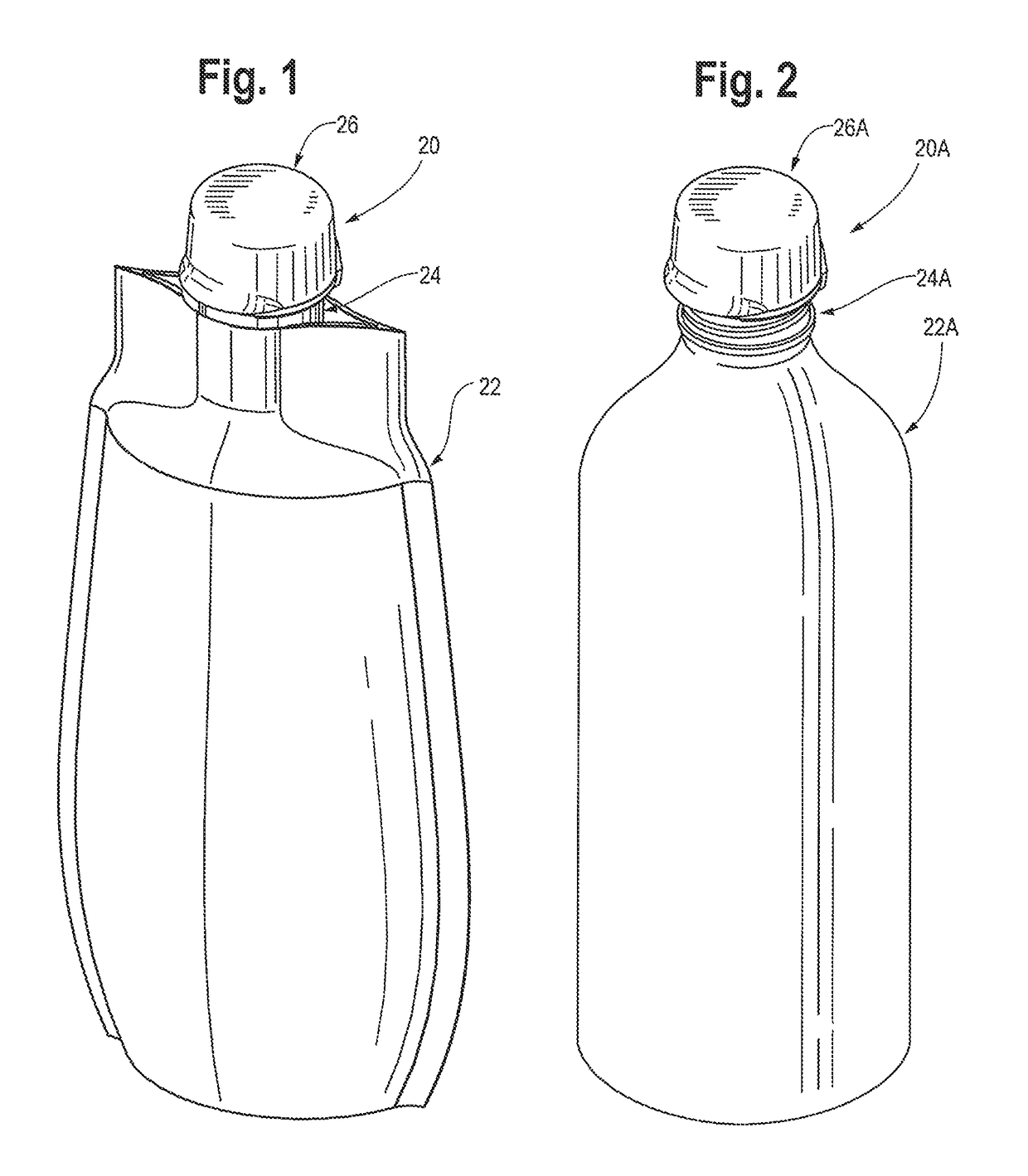
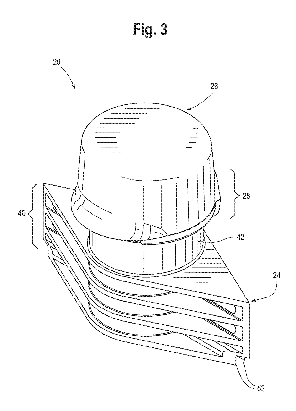
[0036]a closure of the present invention is illustrated in FIGS. 1 and 3-13 wherein the closure is designated generally by reference number 20. In the first illustrated embodiment, the closure 20 is provided in the form of a separate closure which is adapted to be attached to a system in the form of a containment system that would typically contain contents such as a product or products consisting of articles or fluent material.
[0037]The system may be a containment system such as a collapsible, flexible pouch, or may be a generally rigid container (which may have somewhat flexible, resilient walls), such as a bottle or tank. FIG. 1 shows a first embodiment of the closure 20 attached to a containment system that is a collapsible, flexible pouch 22. The system may be some other system which may include, or be part of, for example, a medical device, processing machine, dispenser, reservoir on a machine, etc., wherein the system has an opening to the system interior.
[0038]FIG. 2 shows a...
third embodiment
[0041]In the illustrated embodiments, the closure 20 or 20A (as well as the closure 20B described hereinafter) is provided as a separately manufactured article, component, or unit for being non-removably attached (e.g., mounted or installed) on a system in the form of a containment system defined by a pouch or bottle. It will be appreciated, however, that in some applications (not illustrated), it may be desirable for the closure to be attached to a system in a manner that would allow a user to remove the closure from the system. Further, it may be desirable for the closure for at least the body of the closure) to be formed as a unitary part, or extension, of the system (e.g., a bottle) wherein such a unitary part or extension also (i.e., simultaneously) defines an end structure of the system, per se.
[0042]The illustrated embodiments of the closure, if initially formed separately from the containment system, are adapted to be attached to a containment system at an opening which prov...
second embodiment
[0054]It is presently contemplated that most pouch manufacturers will prefer to install the closure 20 on the pouch 22 with heat sealing techniques or ultrasonic sealing techniques (and most bottlers would prefer to install the closure 20A, as shown in FIG. 2, on a bottle 22A with the closure 20A suitably configured for snap-fit attachment or threaded attachment as explained below). In an alternate installation process, the closure 20 or 20A could be installed on the containment system (e.g., pouch 22 or bottle 22A, respectively) with adhesive.
[0055]The second embodiment of the closure 22A could have a body 24A with various configurations and attachment features (not visible in FIG. 2) that are particularly useful for a container having semi-rigid, resilient walls, or having rigid walls. For example, the closure body 24A could have a cylindrical portion with a thread for threadingly engaging a mating thread of the container 22A (FIG. 2). Alternatively, the closure 20A and container ...
PUM
| Property | Measurement | Unit |
|---|---|---|
| central angle | aaaaa | aaaaa |
| resiliency | aaaaa | aaaaa |
| length | aaaaa | aaaaa |
Abstract
Description
Claims
Application Information
 - R&D
- Intellectual Property
- Life Sciences
- Materials
- Tech Scout
- Unparalleled Data Quality
- Higher Quality Content
- 60% Fewer Hallucinations
Browse by: Latest US Patents, China's latest patents, Technical Efficacy Thesaurus, Application Domain, Technology Topic, Popular Technical Reports.
© 2025 PatSnap. All rights reserved.Legal|Privacy policy|Modern Slavery Act Transparency Statement|Sitemap|About US| Contact US: help@patsnap.com


