
Cutting tool and work machine

a cutting tool and work machine technology, applied in the direction of cutting tools, cutters, horticulture, etc., can solve the problems of adversely affecting the condition of the cutting tool, affecting the cutting tool, and difficult cutting of plant growth beside a timber tree, so as to achieve strong, simple structure, and small working width of the blade part

Active Publication Date: 2018-11-06
BROUWER TURF
View PDF23 Cites 0 Cited by
  • Summary
  • Abstract
  • Description
  • Claims
  • Application Information

AI Technical Summary

Benefits of technology

[0009]The invention is based on transporting the plant growth to the blade part of the cutting tool, which means that the blade part need not be brought in contact with the plant growth to cut it, and the working width of the blade part can be kept small. The cutting tool may be directed more freely to the plant growth to be cut, which means that objects, such as timber trees and soil material, that the blade part should not touch can be kept away from the blade part.
[0010]A cutting tool according to some of the embodiments of the invention is strong and simple in structure to make it durable. This way, the number of maintenance of the cutting blade and the work machine using it can be kept small.

Problems solved by technology

Because the blade cuts with its entire length, which is quite long in relation to the typical diameter of a trunk in the plant growth, the cutting of plant growth beside a timber tree may be very difficult without damaging the timber tree.
On one hand, when managing the blade, it is necessary to pay attention to other objects, such as rocks or other soil material in the terrain which do not necessarily have a commercial value like timber trees but may adversely affect the condition of the cutting tool when they come into contact with the blade.

Method used


Image

  • Cutting tool and work machine
  • Cutting tool and work machine

Examples


Embodiment Construction

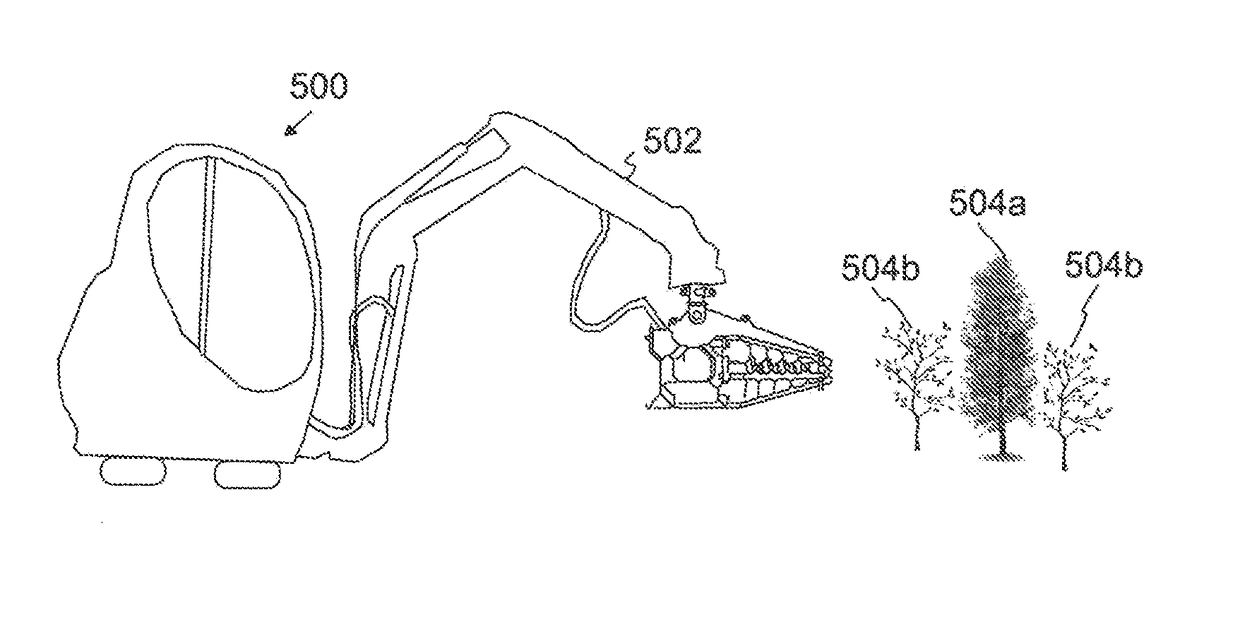
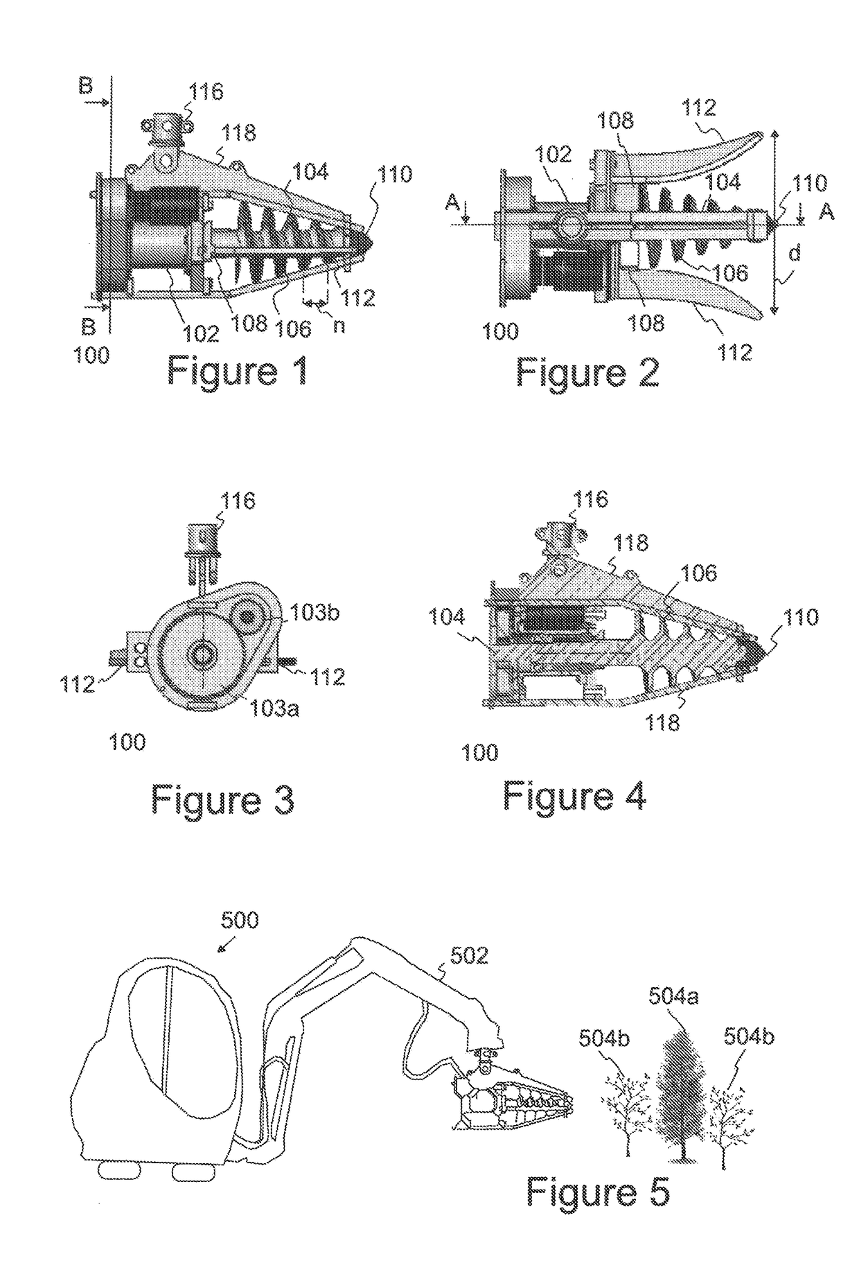
[0017]In the following, cutting tools of some embodiments are described by referring to FIGS. 1 to 4, in which the same or similar objects are depicted with corresponding reference numbers and markings. The cutting tools shown in FIGS. 1 to 4 may illustrate different cutting tools or the same cutting tool. In some embodiments, FIG. 3 shows a cross-section B-B of the cutting tool of FIG. 1 and FIG. 4 shows a cross-section A-A of the cutting tool of FIG. 2. In the following description, the directions up and down are defined in relations to the effect of earth's gravity, which is downward. Thus, gravity defines the vertical direction. Sideways direction is essentially perpendicular to the vertical direction.

[0018]FIGS. 1 to 4 show a cutting tool 100 for clearing plant growth, such as a seeding stand. The cutting tool has a power transmission apparatus 102 and an elongated part 104 coupled thereto to rotate around its own longitudinal axis. The power transmission apparatus may receive ...


PUM


Abstract

A cutting tool for clearing plant growth. The clearing tool includes a power transmission apparatus. An elongated part is coupled to the transmission to rotate around a longitudinal axis of the elongated part and having at least one thread that rises toward the transmission and the diameter of which decreases from an end of the elongated part coupled to the transmission to the end of the elongated part that is at a distance from the transmission. Guide parts are arranged around the elongated part to extend in the direction of the longitudinal axis of the elongated part. A blade part is arranged at the end of the elongated part coupled to the transmission. The elongated part, which, while targeted in a longitudinal direction toward the plant growth, is arranged to cut the plant growth when being rotated, wherein the threads transport the plant growth toward the blade part guided by the guide parts and cut the plant growth with the blade part.

Description

CROSS-REFERENCE TO RELATED APPLICATIONS[0001]The application claims priority to Finnish patent application 20145417 filed 7 May 2014 and is the national phase under 35 U.S.C. § 371 of PCT / FI2015 / 050188 filed 20 Mar. 2015.FIELD OF INVENTION[0002]The invention relates to clearing plant growth, such as a seeding stand, and the cutting tool and work machine used therein.BACKGROUND OF THE INVENTION[0003]Clearing a seeding stand is an essential part of forest management, especially in production forests, in which the objective of forest management is to achieve or even exceed production targets as calculated in the number of timber unit volumes, for example. However, clearing a seeding stand is not limited to production forests only and may also be considered a duty of a forest owner. The purpose of clearing a seeding stand is to ensure that the desired plant growth thrives in the seeding stand by removing the undesired plant growth. If the intention is to grow a spruce forest, seedlings ...

Claims


Application Information

Patent Timeline
Patent Type & Authority Patents(United States)
IPC IPC(8): A01D34/83A01D34/01A01G23/08A01D34/835A01G23/00
CPCA01D34/835A01G23/08A01G23/00A01D34/015A01G23/093A01G3/08A01G23/087
Inventor VALLIUS, LAURI
Owner BROUWER TURF
Learn More