Reactor

a reactor and coil technology, applied in the field of reactors, can solve the problems of generating vibration and noise, affecting the reliability of the reactor, so as to achieve the effect of reducing the stress to be applied to the connection portion between the drawn portion and the terminal, suppressing vibration and noise, and high reliability

Active Publication Date: 2018-10-09
TAMURA KK
View PDF6 Cites 0 Cited by
  • Summary
  • Abstract
  • Description
  • Claims
  • Application Information

AI Technical Summary

Benefits of technology

[0008]The objective of the present invention is to provide a reactor which has a little generation of vibration and noise, and suppresses an application of stress to a connection portion between the coil and an electric circuit by intimately contacting wound portions of the conductive wire forming the coil to obtain an integrated coil, and bonding the coil with a resin cover.
[0023]According to the present invention, since the whole coil is integrated by the self-fusing layer, and the end portions of the coil are stationary fixed to the resin cover by the self-fusing layer, vibrations and noises of the coil are suppressed, stress to be applied to the connection portion between the drawn portion and the terminal is reduced, and thus a highly reliable reactor is accomplishable.

Problems solved by technology

According to conventional reactors that utilize the filler, the filler eliminates a gap between conductive wire portions that form a coil, and a gap between the coil and the resin cover around the core, and thus generation of noises due to vibrations of the conductive wire of the coil and the resin cover when a current flows through the reactor is suppressed.
In the case of reactors that do not utilize the filler, however, such an effect is not accomplished, and thus vibrations and noises may be generated.
In the case of reactors that do not utilize the filler, however, stress may be applied to a connection portion between the coil and the terminal due to vibrations of the coil, possibly causing a break-down in a long-term use.

Method used


Image

  • Reactor
  • Reactor
  • Reactor

Examples


first embodiment

1. First Embodiment

[0033](1) Structure

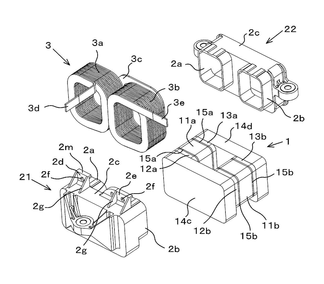
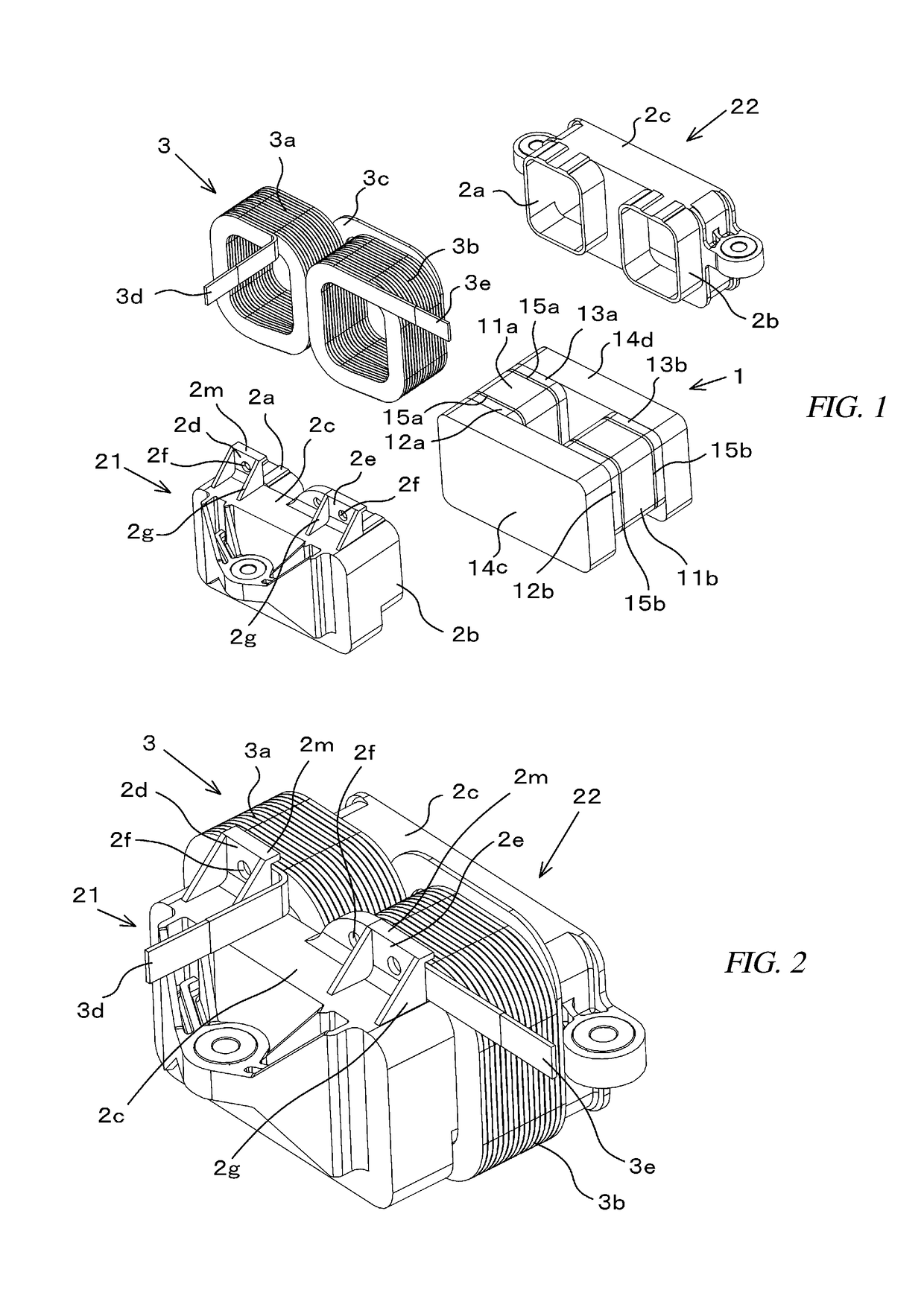
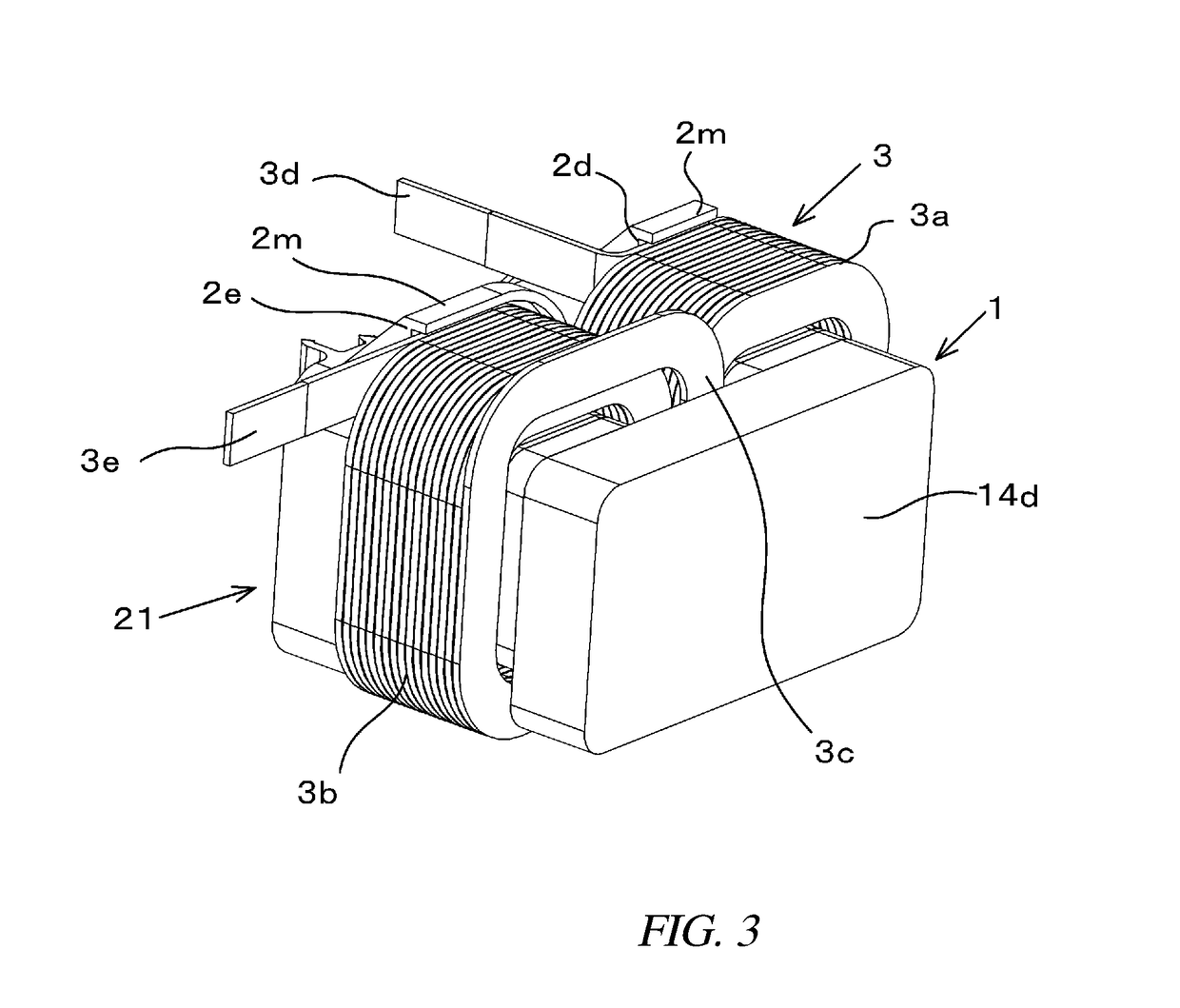
[0034]A reactor according to this embodiment includes an annular core 1, first and second resin covers 21, 22 covering the circumference of the core 1, and a coil 3 attached to the leg portions of the core 1. The annular core 1 is a powder magnetic core formed of pure iron, sendust, or Fe—Si alloy, a ferrite magnetic core, or a magnetic body like laminated steel sheets.

[0035]The annular core 1 includes two thick I-shaped cores 11a, 11b that form the right and left leg portions, four thin I-shaped cores 12a, 13a, 12b, 13b bonded with both sides of the respective thick cores 11a, 11b, and two block-shape cores 14c, 14d that form yokes. Those core pieces are bonded in a rectangular shape. According to this embodiment, spacers 15a, 15b that form respective magnetic gaps are fitted in bonding portions between the two thick I-shaped cores 11a, 11b and the four thin I-shaped cores 12a, 13a, 12b, 13b bonded with both ends of the respective thick cores 1...

second embodiment

2. Second Embodiment

[0065]According to this embodiment, as illustrated in FIG. 5, the wall portions 2d, 2e provided on the resin cover 21 are extended in accordance with the positions of the drawn portions 3d, 3e of the conductive wire as well as the final turn portion of the conductive wire forming the coil 3. This enables a bonding of not only the final turn portion of the conductive wire but also the protruding drawn portions 3d, 3e of the coil 3 with the wall portions 2d, 2e, and thus a further firm fixation of the conductive wire is accomplishable. Consequently, even the connection portions between the drawn portions 3d, 3e and the terminals are apart from each other, vibrations of the drawn portion are efficiently suppressed.

[0066]As explained above, according to this embodiment, the positions of the wall portions 2d, 2e and the shapes thereof are modifiable in accordance with the directions of the drawn portions 3d, 3e and the position of the connection portion with the termi...

third embodiment

3. Third Embodiment

[0067]According to this embodiment, as illustrated in FIG. 6, as the bonding portions, in addition to the upper wall portions 2d, 2e on the upper surface of the first resin cover 21, wall portions 2h that support the drawn portions 3d, 3e of the conductive wire, respectively, are provided at the side faces of the reactor. That is, various positions of the drawn portions 3d, 3e of the conductive wire are expected in accordance with the position of the terminal to be connected to the external electric circuit, and the position of the wall portion 2h is modifiable as appropriate in accordance with the positions of the drawn portions 3d, 3e like this embodiment.


PUM

PropertyMeasurementUnit
melting temperatureaaaaaaaaaa
conductiveaaaaaaaaaa
outer circumferenceaaaaaaaaaa

Abstract

A reactor includes a core, a resin cover provided around the core, and a coil disposed around the core at the external side of the resin cover. The coil includes a conductive wire having a self-fusing layer formed on the surface of the conductive wire, and the adjoining conductive wire portions are bonded together by the self-fusing layer. The resin cover includes a bonding portion provided at a part of the resin cover and facing the end portion of the coil, and the end portion of the coil are bonded with the resin cover by an adhesive at the bonding portion.

Description

CROSS REFERENCE TO RELATED APPLICATIONS[0001]This application claims priority to Japanese Patent Application No. 2015-103960 filed on May 21, 2015, the entire contents of which are incorporated by reference herein.FIELD OF THE INVENTION[0002]The present invention relates to a reactor that has an improved fixation structure for a coil.BACKGROUND[0003]For example, a reactor for a vehicular booster circuit has been known which includes a resin cover (also called a bobbin) that covers the circumference of an annular magnetic core, and a coil provided around the outer circumference of the resin cover.[0004]As disclosed in JP 2014-199872 A and JP 2012-049269 A, according to such a type of conventional reactors, the entire reactor is housed in the casing, and a filler is applied and solidified between the reactor and the casing.[0005]In the case of, for example, vehicular reactors that have a large amount of heat generation when a current flows, it is necessary to improve cooling efficienc...

Claims


Application Information

Patent Timeline
Patent Type & Authority Patents(United States)
IPC IPC(8): H01F27/30H01F27/29H01F27/28H01F27/32
CPCH01F27/2847H01F27/325H01F27/306
Inventor MAENO, KENSUKEYAMADA, MASASHI
Owner TAMURA KK
Why Eureka
Try Eureka