
Double-link piston crank mechanism for internal combustion engine

a technology of internal combustion engine and crank mechanism, which is applied in the direction of crankshafts, machines/engines, crankshafts, etc., can solve the problems of deterioration of achieve the effects of suppressing shape variation (deformation), high rigidity, and improving seizure resistance and abrasion resistance of the crank pin bearing portion

Active Publication Date: 2018-10-02
NISSAN MOTOR CO LTD
View PDF17 Cites 0 Cited by
  • Summary
  • Abstract
  • Description
  • Claims
  • Application Information

AI Technical Summary

Benefits of technology

The present invention provides a crank pin bearing portion with improved rigidity and resistance to seizure and abrasion by having a thicker central portion in the crank shaft axial direction. This helps to prevent shape variations in the crank shaft axial direction and relieves bearing end contacts.

Problems solved by technology

Consequently, the seizure resistance and the abrasion resistance of the crank pin bearing portion may be deteriorated.

Method used


Image

  • Double-link piston crank mechanism for internal combustion engine
  • Double-link piston crank mechanism for internal combustion engine
  • Double-link piston crank mechanism for internal combustion engine

Examples


Embodiment Construction

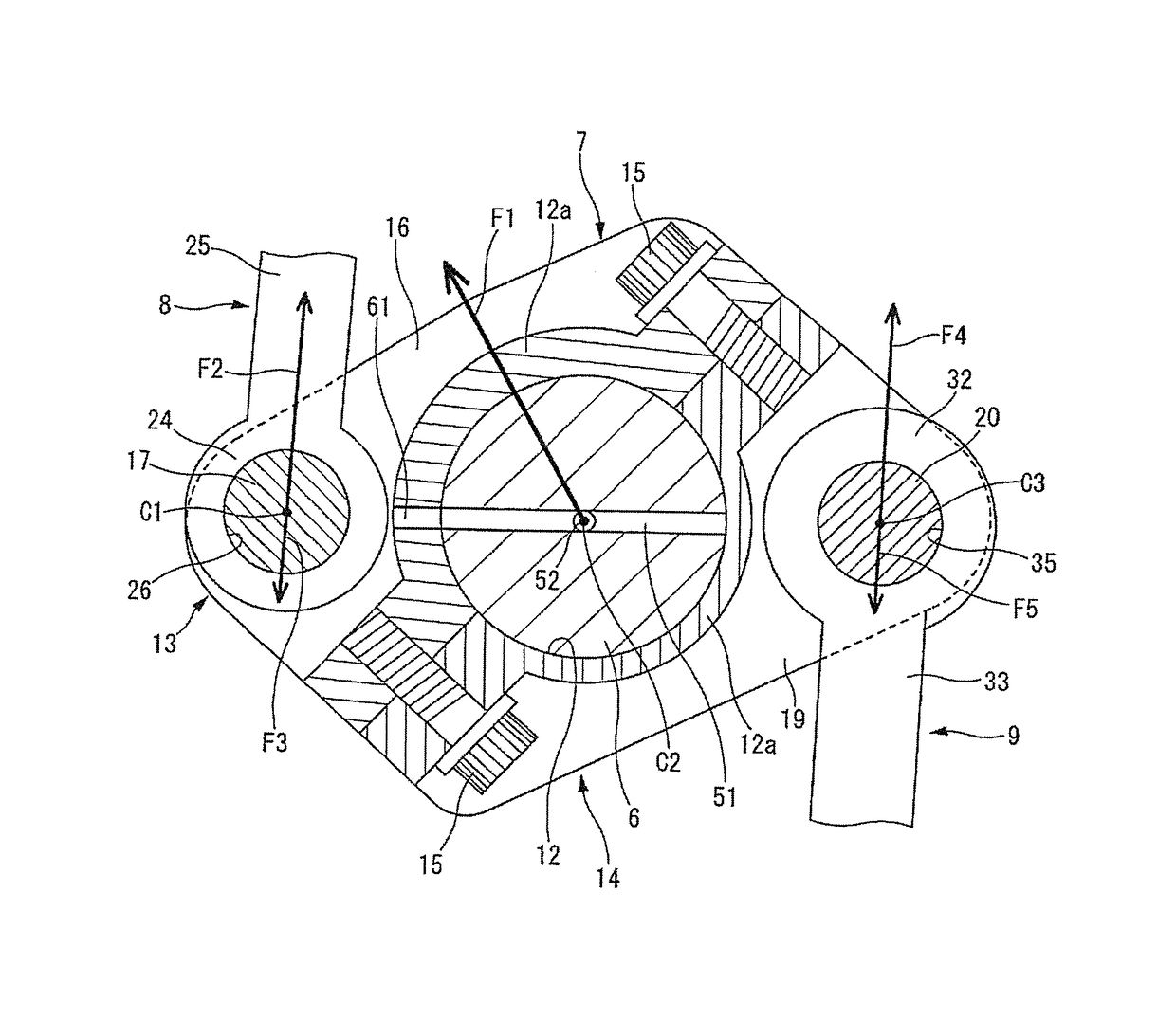
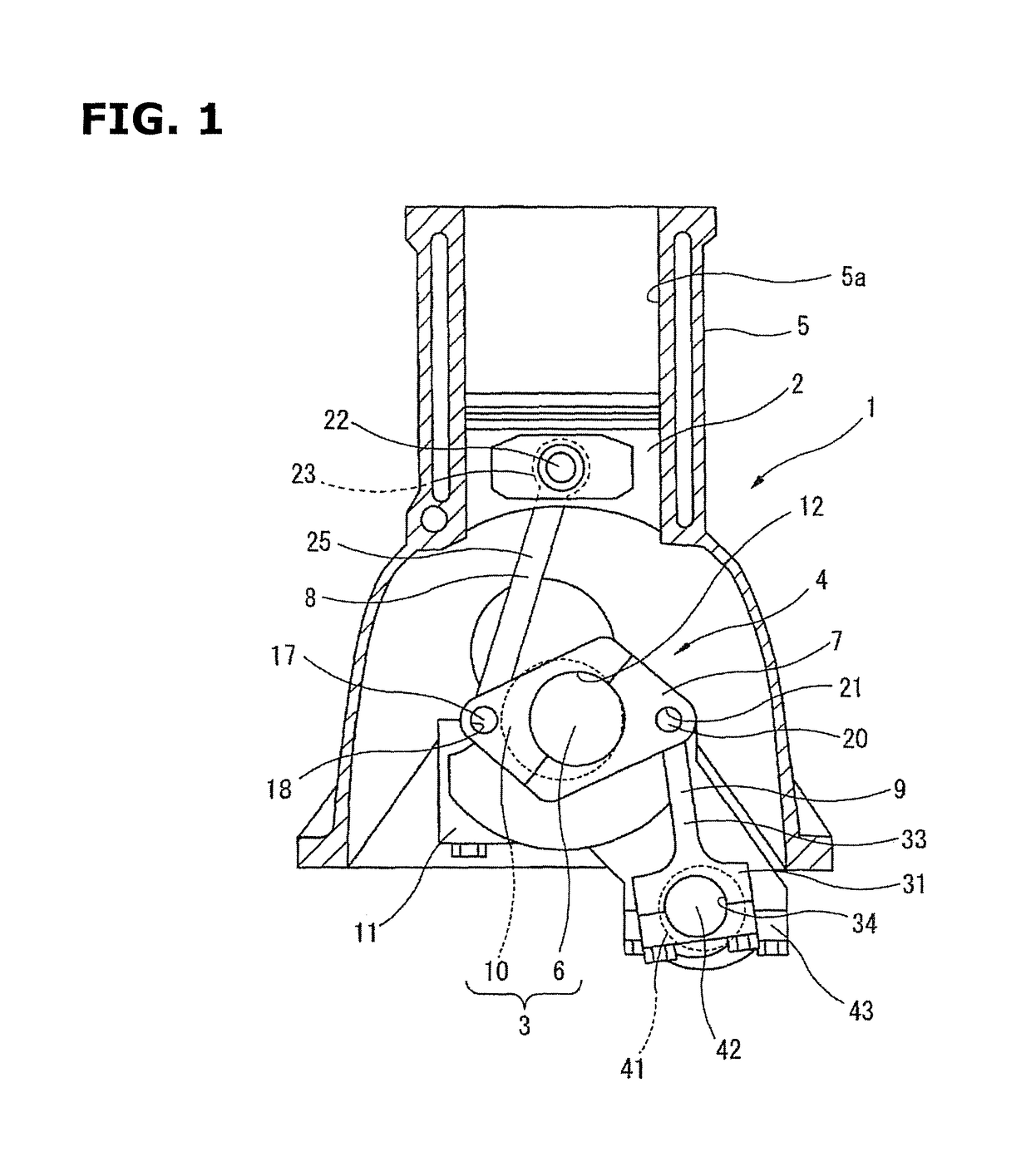
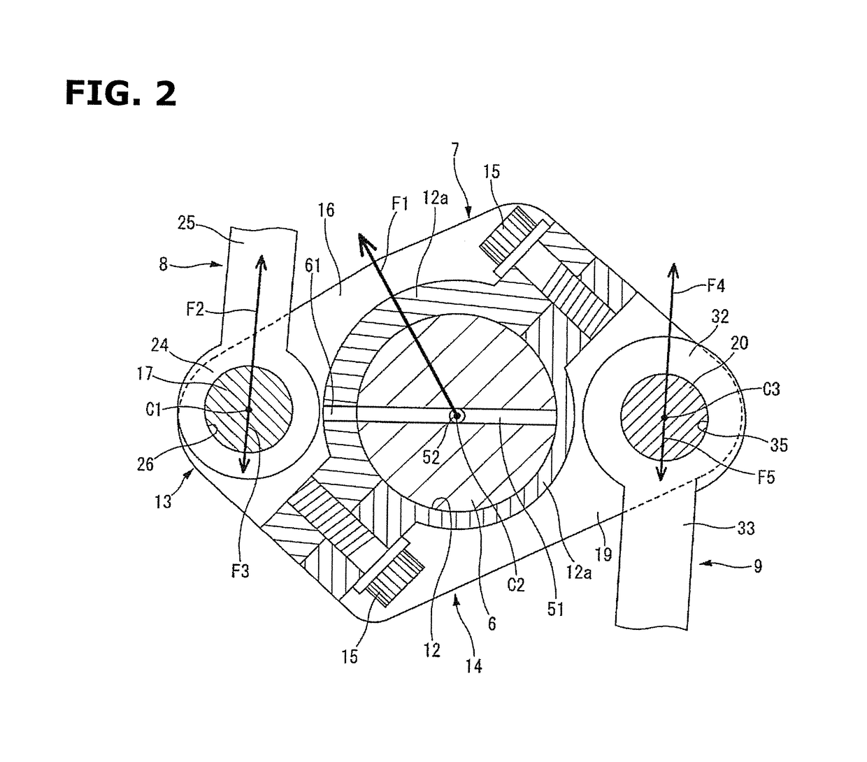
[0021]Hereinafter, embodiments of the present invention are described in detail with reference to the drawings. In embodiments of the invention, numerous specific details are set forth in order to provide a more thorough understanding of the invention. However, it will be apparent to one of ordinary skill in the art that the invention may be practiced without these specific details. In other instances, well-known features have not been described in detail to avoid obscuring the invention. FIG. 1 is an explanatory view schematically showing an internal combustion engine 1 including one or more embodiments of the present invention.

[0022]An internal combustion engine 1 includes a multi-link piston crank mechanism (double-link piston crank mechanism) 4 by which a piston 2 and a crank shaft 3 are linked with each other by a plurality of links. The multi-link piston crank mechanism 4 in one or more embodiments of the present invention is a variable compression ratio mechanism arranged to ...


PUM


Abstract

A multi-link piston crank mechanism includes a crank pin bearing portion including a crank pin bearing central portion that is disposed at a center thereof in an axial direction of a crank shaft. The crank pin bearing central portion at a portion positioned on the first end side of the lower link is thicker in a radial direction of the crank pin than a portion positioned on the second end side of the lower link. The second control link end portion is thicker along a radial direction of the second through hole than the second upper link end portion along a radial direction of the first through hole.

Description

BACKGROUNDTechnical Field[0001]This invention relates to a multi-link piston crank mechanism of an internal combustion engine.Related Art[0002]Conventionally, there is known a multi-link piston crank mechanism in which a piston and a crank pin of a crank shaft are linked through a plurality of links.[0003]For example, a patent document 1 discloses a piston crank mechanism for an internal combustion engine which includes an upper link including one end connected through a piston pin to the piston, a lower link connected through an upper pin to the other end of the upper link, and rotatably connected to the crank pin of the crank shaft at the crank pin bearing portion, and a control link including one end swingably supported by the engine main body, and the other end connected through a control pin to the lower link.[0004]The lower link in this patent document 1 includes an upper pin boss portion and a control pin boss portion which are located on the both sides of the crank pin beari...

Claims


Application Information

Patent Timeline
Patent Type & Authority Patents(United States)
IPC IPC(8): F02B75/04F16C3/30F16C11/02F02B75/32F01M1/06F16C3/14F01M1/02
CPCF02B75/045F01M1/06F02B75/32F16C3/30F16C11/02F16C3/14F01M2001/062F01M1/02F02B75/04
Inventor TANABE, TAKASHIMOTEKI, KATSUYA
Owner NISSAN MOTOR CO LTD
Learn More