Tank manufacturing method, helical winding device, and filament winding apparatus

a manufacturing method and technology of filament winding, applied in the field of fiber bundle winding technology, can solve the problem that the strength of a manufactured tank cannot be improved sufficiently, and achieve the effect of reducing the gap, broadening the width of the first fiber bundle, and increasing the swinging rang

Active Publication Date: 2018-10-02
TOYOTA JIDOSHA KK +1
View PDF18 Cites 0 Cited by
  • Summary
  • Abstract
  • Description
  • Claims
  • Application Information

AI Technical Summary

Benefits of technology

[0011]One aspect of the present invention provides a tank manufacturing method using a helical winding device that winds fiber bundles around a mandrel by helical winding. The helical winding device includes a first guide ring having an opening to pass the mandrel therethrough and placed around the mandrel with an axial center of the mandrel being taken as a center, and a plurality of first guide portions placed in the first guide ring along a circumferential direction around the axial center and configured to supply first fiber bundles to the mandrel. The tank manufacturing method includes: moving the mandrel relative to the first guide ring in an axial center direction along the axial center such that the mandrel passes through the opening; and winding the fiber bundles around the mandrel while relatively moving the mandrel in the moving, by the first guide portions supplying the fiber bundles to the mandrel with the first guide portions swinging in the circumferential direction. According to the tank manufacturing method of the present aspect, the first guide portions wind the first fiber bundles around the mandrel while the first guide portions are swinging in the circumferential direction. This makes it possible to broaden a width of the first fiber bundles thus wound. This makes it possible to reduce occurrence of a gap between fiber bundles adjacent to each other.
[0019]In the helical winding device of the above aspect, the swing mechanism may increase a swinging range of the first guide portions in the circumferential direction as a diameter of the mandrel becomes larger. According to the helical winding device of the above aspect, by increasing the swinging range, it is possible to further broaden the width of the first fiber bundles. Accordingly, even if a diameter of a part where the fiber bundles are wound changes, it is possible to reduce a gap between adjacent fiber bundles appropriately according to the part where the fiber bundles are wound.

Problems solved by technology

When the gap is caused between the fiber bundles thus wound around the mandrel, such a possibility occurs that strength of a manufactured tank cannot be improved sufficiently.

Method used


Image

  • Tank manufacturing method, helical winding device, and filament winding apparatus
  • Tank manufacturing method, helical winding device, and filament winding apparatus
  • Tank manufacturing method, helical winding device, and filament winding apparatus

Examples


embodiment

A. Embodiment

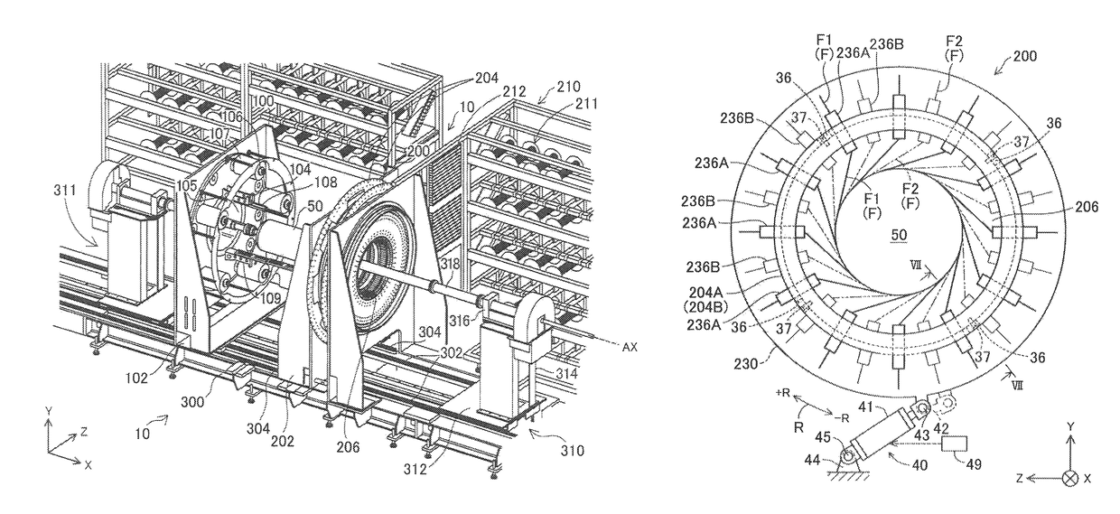
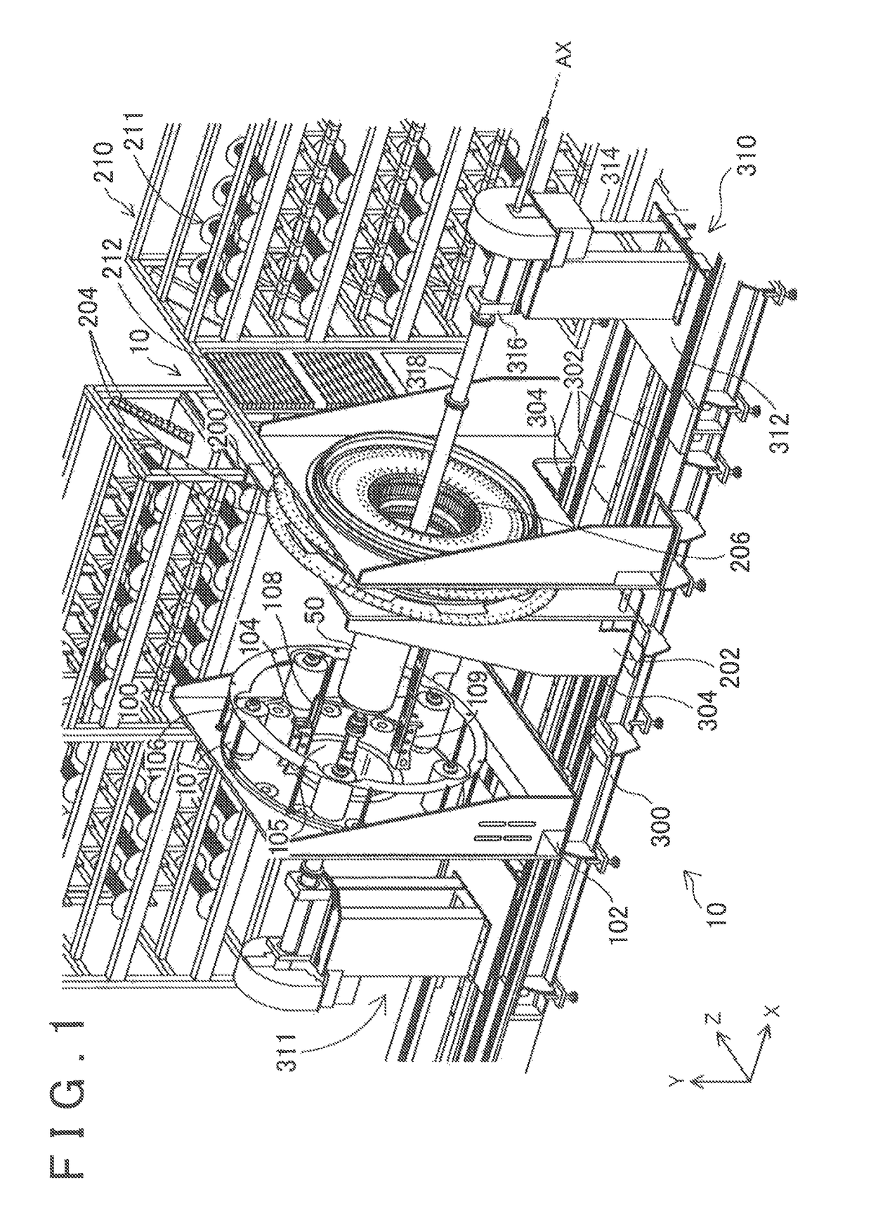
[0032]FIG. 1 is a perspective view illustrating an appearance configuration of a fiber winding apparatus as one embodiment of the present invention. A fiber winding apparatus 10 is an apparatus that winds fiber bundles around a mandrel 50 by a filament winding method. In the present embodiment, the fiber bundle to be wound around the mandrel 50 is formed by bundling a plurality (e.g., 20,000) of filaments having a diameter of around several micrometers. Further, the fiber bundle is a set of carbon fibers (so-called prepreg) impregnated with thermo setting resin. In the present embodiment, epoxy resin is used as the thermo setting resin. Further, in the present embodiment, polyacrylonitrile (PAN) carbon fiber is used as the carbon fiber. Note that, instead of polyacrylonitrile (PAN) carbon fiber, other given prepregs such as rayon carbon fiber and pitch carbon fiber can be used.

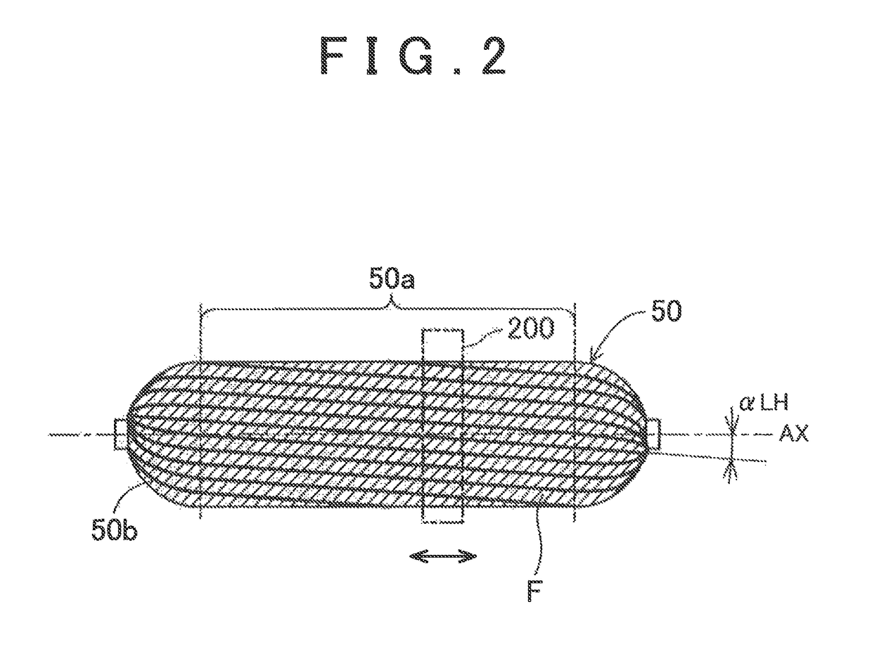
[0033]The mandrel 50 is constituted by a resin molded product in the present embodiment. Note ...

first modification

B-1. First Modification

[0075]In the above embodiment, members having the frame-shaped tip opening 239 are used as the first and second guide portions 236A, 236B. However, the present invention is not limited to this. For example, those parts of the first and second guide portions 236A, 236B which guide the fiber bundles F may be formed in a tubular shape.

second modification

B-2. Second Modification

[0076]As illustrated in FIG. 10, the thickness Ta of the first fiber bundle F1 used herein is thinner than the thickness Tb of the second fiber bundle F2. However, the present invention is not limited to this. The first fiber bundle F1 and the second fiber bundle F2 may have the same thickness, or the thickness Tb may be thinner than the thickness Ta.


PUM

PropertyMeasurementUnit
fiber angle αLHaaaaaaaaaa
fiber angle α0aaaaaaaaaa
thicknessaaaaaaaaaa

Abstract

In a tank manufacturing method using a helical winding device that winds fiber bundles around a mandrel, the device includes: a first guide ring having an opening to pass the mandrel therethrough and placed around the mandrel with an axial center of the mandrel being taken as a center; and a plurality of first guide portions placed in the first guide ring along a circumferential direction around the axial center and configured to supply first fiber bundles to the mandrel. The method includes: moving the mandrel relative to the first guide ring along an axial center direction along the axial center such that the mandrel passes through the opening; and winding the fiber bundles around the mandrel while relatively moving the mandrel in the moving, by the first guide portions supplying the first fiber bundles to the mandrel with the first guide portions swinging in the circumferential direction.

Description

INCORPORATION BY REFERENCE[0001]The disclosure of Japanese Patent Application No. 2014-100264 filed on May 14, 2014 including the specification, drawings and abstract is incorporated herein by reference in its entirety.BACKGROUND OF THE INVENTION[0002]1. Field of the Invention[0003]The present invention relates to a technique to wind fiber bundles around a mandrel.[0004]2. Description of Related Art[0005]There has been known a so-called large-supply helical winding device that supplies fiber bundles to a mandrel from a plurality of guide portions (for example, Japanese Patent Application Publication No. 2009-119803 (JP 2009-119803 A)). The helical winding device described in JP 2009-119803 A includes: a group of guide tubes placed at even intervals along a circumferential direction of a guide ring; and a phase switching structure that changes a circumferential position of the group of guide tubes between a first position (a position in a first state) and a second position (a positio...

Claims


Application Information

Patent Timeline
Patent Type & Authority Patents(United States)
IPC IPC(8): B65H81/00B29C53/66
CPCB29C53/66B65H81/00
Inventor HATTA, KENTANIGAWA, MOTOHIRONAKAMURA, DAIGORO
Owner TOYOTA JIDOSHA KK
Why Eureka
Try Eureka