Wave energy conversion apparatus

a technology of wave energy and equipment, applied in the direction of machines/engines, vessel construction, marine propulsion, etc., can solve the problems of reducing or destructing the efficiency of energy conversion, and achieve the effect of reducing unwanted shear and bending forces

Active Publication Date: 2018-09-25
HAAHEIM INVENT
View PDF4 Cites 0 Cited by
  • Summary
  • Abstract
  • Description
  • Claims
  • Application Information

AI Technical Summary

Benefits of technology

[0010]The invention is particularly, but not exclusively, advantageous for obtaining a wave energy conversion apparatus that efficiently converts wave energy from waves of varying sizes and waves coming from multiple directions. Further, the floatable compliant vessel is a self-supporting structure wherein the energy conversion takes place decentrally in each of the linear generators. The energy conversion means also ensures the structural integrity of the construction, hence no additional support structure is necessary. The external forces acting on the floatable compliant vessel is hereby distributed throughout the construction and the construction becomes very dynamic. As the construction does not have one particular mode of operation or preferred pattern of movement, wave energy may be generated from waves of varying sizes and waves coming from multiple directions. This contributes to an efficient power production as many different types of waves can be converted efficiently. Also, the construction becomes more robust, both towards wear and tear but also with regard to sudden or momentary large impacting forces. Still further, the dynamic character of the compliant frame structure is supported by the spring back means constantly forcing the linear generators towards their neutral position. Hereby the compliant vessel constantly moves under the influence of the waves, but without ending up in undesirable extreme positions, which may be destructive or reduce the efficiency of the energy conversion. Further, the structure keeps itself buoyant, and does not rely on other structures such as flotation units to stay afloat
[0014]Further, the outer flexible membrane is watertight and encloses the compliant frame structure so that water is prevented from entering the inner air filled space of the floatable compliant vessel, thereby maintaining its buoyancy and a dry environment for equipment located in the inner space of the floatable compliant vessel.
[0015]Furthermore, the inner space of the floatable compliant vessel may be substantially air tight and depressurised whereby the compliant frame structure is subject to a compression force by the outer flexible membrane urging the linear generators into a neutral position. Providing a negative pressure relative to the atmospheric pressure inside the floatable compliant vessel, is a way of adjusting the compression and / or elongations of the linear generators, and can thus be used to control the steady-state condition of the floatable compliant vessel. Further, by adjusting the pressure inside the inner space, the manipulability of the compliant vessel may be controlled.
[0025]Moreover, the outer flexible membrane may be displaceably arranged in relation to the compliant frame structure, allowing points of contact between the compliant frame structure and the outer flexible membrane to shift. Also, at least some of the pivot joints may comprise ball-shaped supporting surfaces constituting points of contact between the compliant frame structure and the outer flexible membrane. In addition, the outer flexible membrane may comprise multiple sections of elasticity and / or flexibility.
[0027]According to another aspect of the invention, at least some of the plurality of linear generators is arranged in the compliant frame structure in a tetrahedral geometry having groups of linear generators extending from a common pivot joint. Additionally, an angle between two linear generators extending from the same common pivot joint may be approximately 109 degrees. The linear generators thereby form a frame structure similar to that of carbon atoms in a diamond lattice. Further, this structure minimizes unwanted shear and bending forces on the linear generators since they are aligned so that incoming waves will not act perpendicular to the longitudinal axis of the linear generators.
[0032]Additionally, the wave energy conversion apparatus described above may further comprise a mooring system to secure the wave energy conversion apparatus against drifting.

Problems solved by technology

Hereby the compliant vessel constantly moves under the influence of the waves, but without ending up in undesirable extreme positions, which may be destructive or reduce the efficiency of the energy conversion.

Method used


Image

  • Wave energy conversion apparatus
  • Wave energy conversion apparatus
  • Wave energy conversion apparatus

Examples


Embodiment Construction

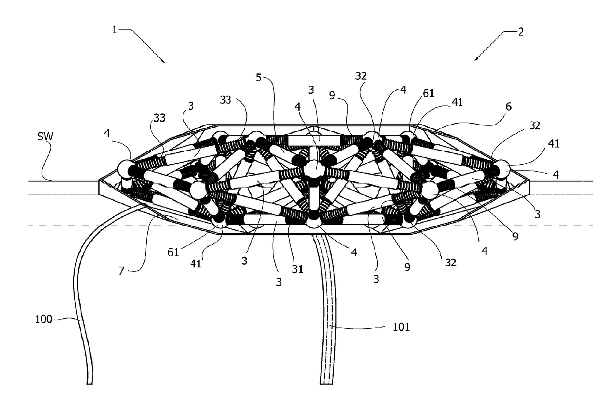
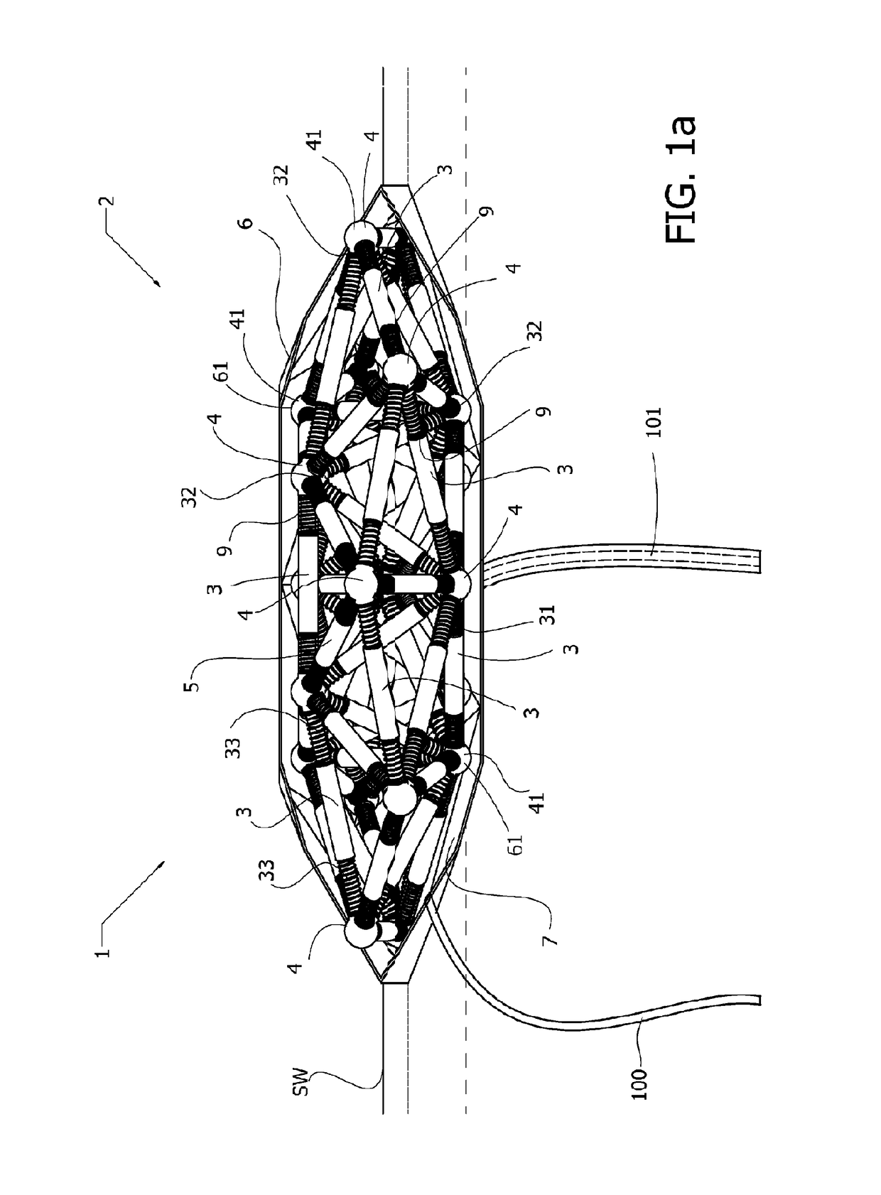
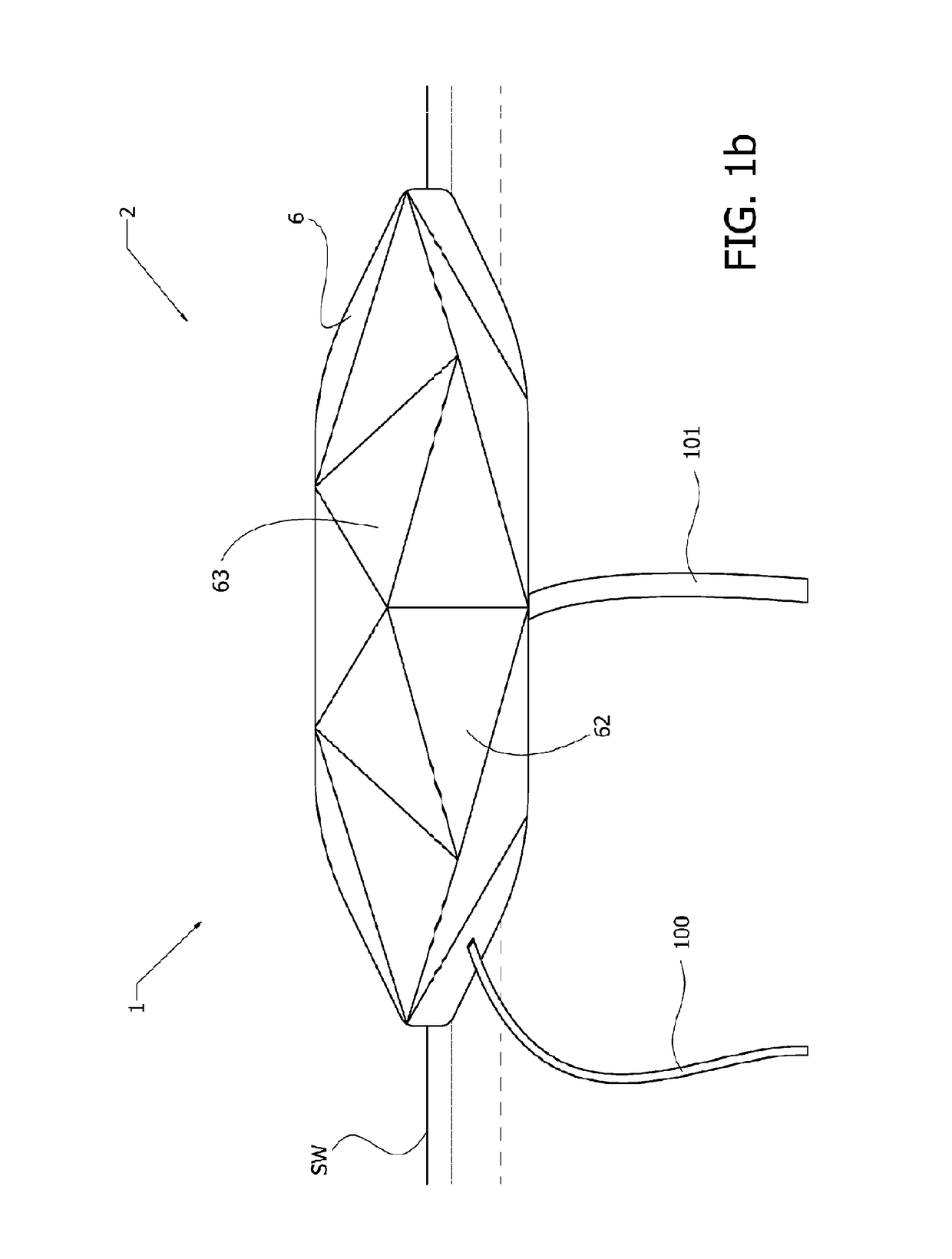
[0052]FIGS. 1a and 1b show a wave energy conversion apparatus 1 according to one aspect of the invention comprising a floatable compliant vessel 2. The floatable compliant vessel is shown to be semi-submerged in the sea SW, and provided with a power transmission line 101 and means of external fixation means 100, such as a mooring system, extending downwards. The floatable compliant vessel 2 comprises a compliant frame structure 5 enclosed by an outer flexible membrane 6. The outer flexible membrane defines an inner air filled space 7 of the floatable compliant vessel and as the outer flexible membrane 6 is supported and stretched by the compliant frame structure 5, a floatable vessel is provided.

[0053]The compliant frame structure comprises a plurality of linear generators 3 linked via a plurality of pivot joints 4. The ends 32 of the linear generators are hinged to the pivot joints 4 so that no bending forces are transmitted, allowing the mutual angular orientation of the linear ge...


PUM


Abstract

The present invention relates to a wave energy conversion apparatus for converting wave energy into a power output, comprising a floatable compliant vessel having a plurality of linear generators having ends which are interconnected at a plurality of pivot joints to provide a compliant frame structure, the plurality of linear generators being configured to produce a power output by being respectively compressed and elongated changing the relative positions of the pivot joints, an outer flexible membrane supported by and enclosing the compliant frame structure thereby defining an inner space of the floatable compliant vessel, and a power circuit arranged within the inner space and operationally connected to the linear generators to receive the power output generated by the linear generators.

Description

FIELD OF THE INVENTION[0001]The present invention relates to a wave energy conversion apparatus for converting wave energy into a power output, comprising; a semi-submersible floatable compliant vessel having a plurality of linear generators having ends which are interconnected at a plurality of pivot joints to provide a compliant frame structure, the plurality of linear generators being configured to produce a power output by being respectively compressed and elongated thereby changing the relative positions of the pivot joints, an outer flexible membrane supported by and enclosing the compliant frame structure thereby defining an inner air filled space of the floatable compliant vessel, and a power circuit arranged within the inner space and operationally connected to the linear generators to receive the power output generated by the linear generators. The present invention further relates to a system for converting wave energy and use of a wave energy conversion apparatus.BACKGRO...

Claims


Application Information

Patent Timeline
Patent Type & Authority Patents(United States)
IPC IPC(8): F03B13/10F03B13/18F03B13/16F03B13/12H02K7/18B63B35/44B63H19/02F03B13/20
CPCF03B13/16B63B35/44B63H19/02F03B13/188H02K7/1876F03B13/20Y02E10/38B63B2035/4466F05B2220/707F05B2240/93Y02E10/30
Inventor HAAHEIM, OYVIND
Owner HAAHEIM INVENT
Why Eureka
Try Eureka