
Vaporizer apparatus

a technology of vaporizer and cylinder, which is applied in the direction of inhalators, ohmic-resistance heating, other medical devices, etc., can solve the problems of unstable electrical contacts, difficult to determine, and the cylindrical shape may not be optimal, so as to prevent rolling and ensure mechanical and electrical connection. the effect of robustness

Active Publication Date: 2018-09-18
JLI NAT SETTLEMENT TRUST
View PDF3567 Cites 45 Cited by
  • Summary
  • Abstract
  • Description
  • Claims
  • Application Information

AI Technical Summary

Benefits of technology

The patent describes a vaporizer apparatus that includes a cartridge with a mouthpiece and a detent mechanism to secure the cartridge in place. The cannula helps regulate the temperature of the vapor by forming a passage for the vapor from the heater to the mouthpiece. The cannula is visible through a window in the tank, which also helps users understand the level of vaporizable material within the tank. The mouthpiece is opaque and fits over the top of the transparent tank, allowing users to easily see the level of vaporizable material. The patent also describes the elongated shape of the vaporizer, which prevents it from rolling on a table or in a user's mouth. The heater contacts are designed to protect the heater and absorb excessive heat. The technical effects of the vaporizer apparatus include improved vaping experience, a visual reference for the liquid level in the tank, and a secure and robust mechanical and electrical connection between the cartridge and the vaporizer.

Problems solved by technology

Although mimicking the cylindrical look of traditional cigarettes may have marketing advantages because of a preexisting familiarity with this shape and potentially feel of the product, the cylindrical shape may not be optimal.
However, a number of surprising disadvantages may result in this configuration.
For example the use of a cartridge at the proximal end of the device, which is also held by the users mouth, has been found to cause instability in the electrical contacts, particularly with cartridges of greater than 1 cm length.
Further, there may be difficulties in determining the amount of vaporizable material within the cartridge, sufficiently cooling or otherwise processing the vapor generated by a heater located in the cartridge, and easily and quickly securing the cartridge into the vaporizer when force may be applied by a user's mouth at the proximal mouthpiece when a user holds the device either just by the mouth or using the mouth at the proximal end and a hand on the more distal body of the vaporizer.

Method used


Image

  • Vaporizer apparatus
  • Vaporizer apparatus
  • Vaporizer apparatus

Examples


examples

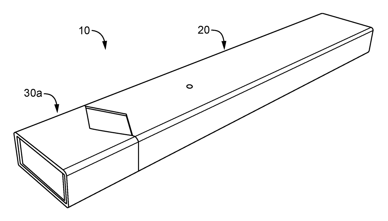
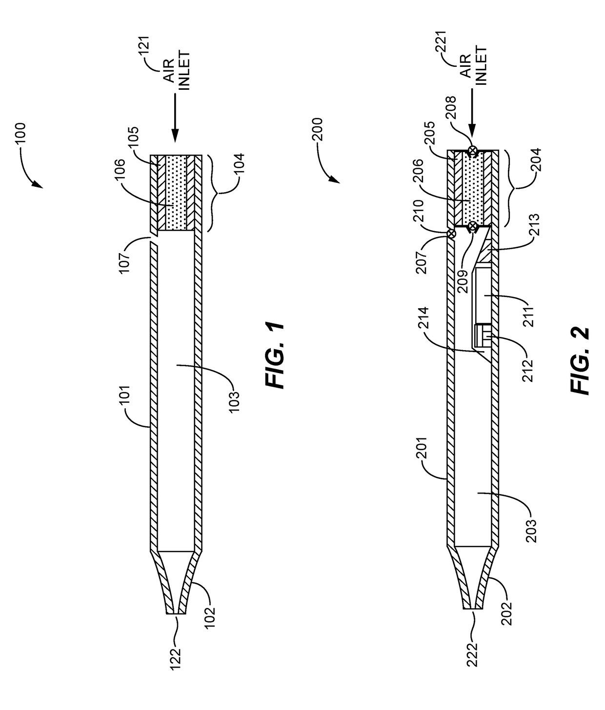
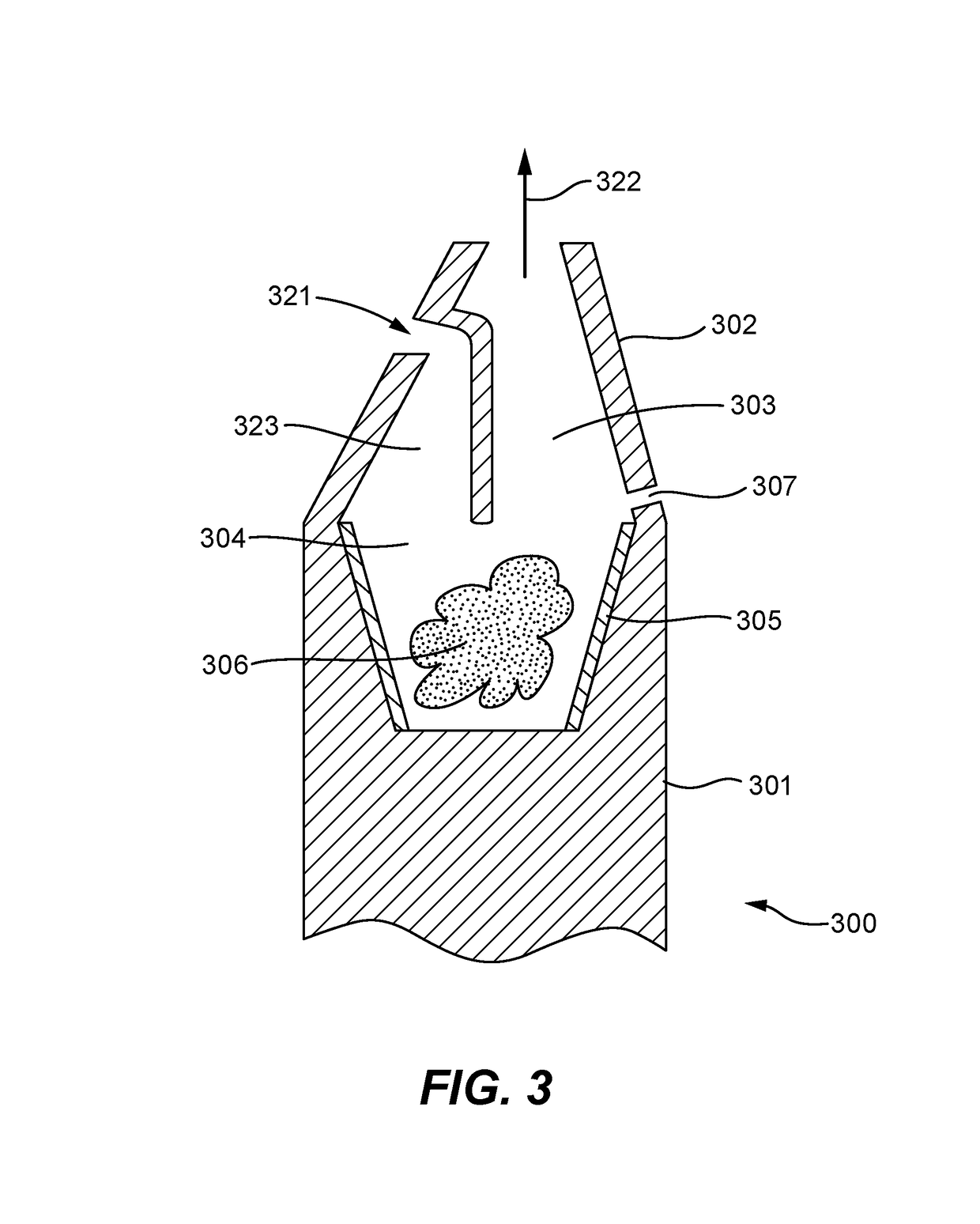
[0350]Any of the cartridges described in the figures and description above may include an elongate and flattened storage compartment for holding a vaporizable material and a mouthpiece at the proximal end of cartridge. In particular, FIGS. 5-7B, 8B, 9, 11-15, and 16C show examples of a cartridge for use with a vaporizer device that includes an elongate and flattened storage compartment (see, element 32 in FIG. 7B and element 32a in FIGS. 9A-9L) configured to hold a liquid vaporizable material, wherein the liquid vaporizable material is visible through the storage compartment, further wherein the storage compartment comprises a distal end and a proximal end, and a first side extending between the distal end and the proximal end. In each of these examples the cartridge also includes an opaque mouthpiece (e.g., 31 in FIGS. 7B and 8B) that is secured over the proximal end of the storage compartment, the opaque mouthpiece having a front side adjacent to the first side of the storage comp...


PUM


Abstract

Vaporizer devices and apparatuses are provided. In some implementations, an apparatus comprises a cartridge and a vaporizer body. The cartridge comprises a storage compartment configured to hold a vaporizable material, a heater comprising a resistive heating element for generating an aerosol, and a mouthpiece comprising an opening for passage of the aerosol. The vaporizable material is visible through at least one side of the storage compartment. The vaporizer body comprises a proximal end, a distal end opposite the proximal end, and a cartridge receptacle at the proximal end, the cartridge receptacle configured to house the cartridge. The cartridge receptacle comprises a notch extending from the proximal end towards the distal end, and a portion of the storage compartment is visible through the notch when the cartridge is housed in the cartridge receptacle.

Description

CROSS REFERENCE TO RELATED APPLICATIONS[0001]This patent application claims priority as a continuation-in-part of U.S. patent application Ser. No. 14 / 581,666, filed Dec. 23, 2014, and titled “VAPORIZATION DEVICE SYSTEMS AND METHODS”, which claimed priority to U.S. Provisional Patent Application No. 61 / 920,225, filed Dec. 23, 2013, and titled “ELECTRONIC VAPORIZATION DEVICE WITH RAPID COOLING AERATION”, U.S. Provisional Patent Application No. 61 / 936,593, filed Feb. 6, 2014, and titled “ELECTRONIC CIGARETTE JUICE DEVICE,” U.S. Provisional Patent Application No. 61 / 937,755, filed Feb. 10, 2014, and titled “ELECTRONIC CIGARETTE JUICE DEVICE”. Each of these patent applications is herein incorporated by reference in its entirety.[0002]This patent application also claims priority to U.S. Provisional Patent Application No. 62 / 294,285, filed Feb. 11, 2016, and titled “FILLABLE ELECTRONIC CIGARETTE CARTRIDGE AND METHOD OF FILLING” and U.S. Provisional Patent Application No. 62 / 294,281, filed ...

Claims


Application Information

Patent Timeline
Patent Type & Authority Patents(United States)
IPC IPC(8): A24F47/00A61M11/04H05B1/02H05B3/44A61M15/06A24F40/10A24F40/40A24F40/60
CPCA24F47/008H05B1/0244H05B3/44A61M15/06A61M11/042H05B2203/021H05B2203/022A61M2205/3653A61M2205/8206A24F40/10A24F40/60A24F40/40A24F40/42
Inventor MONSEES, JAMESBOWEN, ADAMCHRISTENSEN, STEVENMORENSTEIN, JOSHUAHIBMACRONAN, CHRISTOPHER NICHOLAS
Owner JLI NAT SETTLEMENT TRUST
Learn More