Tool calibration apparatus of robot manipulator

a robot manipulator and tool calibration technology, which is applied in the field of tool calibration apparatus, can solve the problems of degrading the accuracy of the tool calibration performed by the conventional tool calibration apparatus with infrared sensors, the inability to accurately measure and acquire the displacement variations of the tool relative to the end effector of the robot manipulator, and the high cost of the conventional tool calibration apparatus equipped with infrared sensors. achieve the effect of reducing cost, saving operating time and saving measurement and acquisition accuracy

Active Publication Date: 2018-09-04
DELTA ELECTRONICS INC
View PDF20 Cites 2 Cited by
  • Summary
  • Abstract
  • Description
  • Claims
  • Application Information

AI Technical Summary

Benefits of technology

[0007]It is an object of the present invention to provide a tool calibration apparatus of a robot manipulator with reduced cost and capable of being module-assembled. The displacement variations of the TCP of the tool relative to the end effector of the robot manipulator can be measured and acquired accurately by the inventive tool calibration apparatus, so that the robot manipulator can compensate for the tool inaccuracy rapidly to secure the correct operating position of the tool. Consequently, the operating time can be saved as comparing with manual calibration, and high-precision calibration of the tool can be achieved by using the inventive tool calibration apparatus.

Problems solved by technology

However, the conventional tool calibration apparatus equipped with infrared sensors is extremely expensive.
However, when one tool mounted to the robot manipulator is replaced with another one with different type, the displacement variations of the TCP of the tool relative to the end effector of the robot manipulator can't be acquired accurately by the conventional tool calibration apparatus with infrared sensors.
Consequently, the accuracy of the tool calibration performed by the conventional tool calibration apparatus is degraded.
In addition, the misalignment of the tool may shut down the entire production line and waste material, time and cost.

Method used


Image

  • Tool calibration apparatus of robot manipulator
  • Tool calibration apparatus of robot manipulator
  • Tool calibration apparatus of robot manipulator

Examples


first embodiment

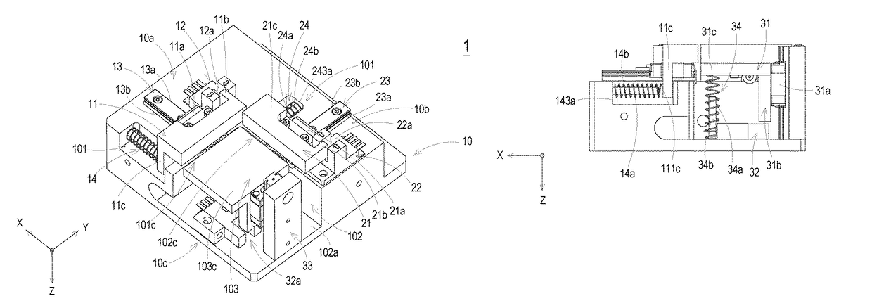
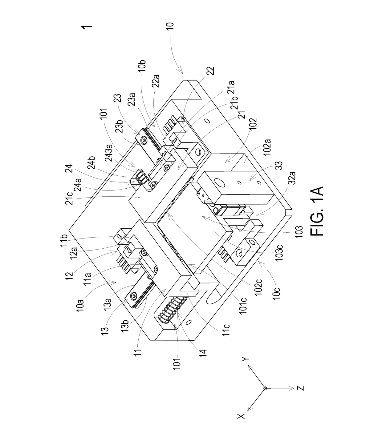
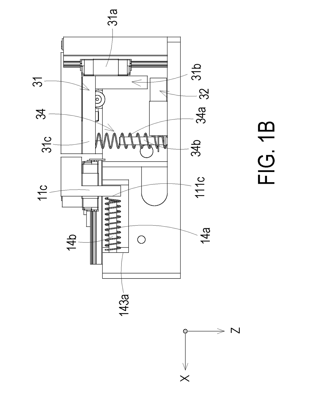
[0024]FIG. 1A is a schematic perspective view illustrating a tool calibration apparatus of a robot manipulator according to the present invention, FIG. 1B is a schematic perspective view illustrating the tool calibration apparatus of FIG. 1A in different angle of view, FIG. 2A is a schematic view showing that a tool mounted to the robot manipulator is applied to the tool calibration apparatus of the present invention, and FIG. 2B is a partial enlargement schematic view of FIG. 2A. As shown in FIGS. 1A, 1B, 2A and 2B, the tool calibration apparatus 1 is employed to calibrate the tool 3, which is mounted to the distal end of the robot manipulator 2, for ensuring that the tool 3 always be operated at the correct positions when the robot manipulator 2 performs a required task. Preferably but not exclusively, the robot manipulator is a selective compliance assembly robot arm (SCARA). The tool calibration apparatus 1 comprises a base 10, an X-axis measurement device 10a, a Y-axis measurem...

second embodiment

[0038]FIG. 4A is a schematic perspective view illustrating a tool calibration apparatus according to the present invention, and FIG. 4B is a schematic perspective view illustrating the tool calibration apparatus of FIG. 4A in different angle of view. In comparison with the tool calibration apparatus 1 of FIGS. 1A and 1B, the first spring 14a and the second spring 24a of the tool calibration apparatus 1a of this embodiment are disposed at different locations. One end of the first spring 14a is secured to a first side surface 144a of the recess 101, and the other end of the first spring 14a is secured to an inner surface 112c of the first sidewall 11c. When the first measuring plate 11 is moved in a direction along the X-axis, the first sidewall 11c of the first measuring plate 11 is moved correspondingly. Consequently, the first spring 14a is stretched by the first sidewall 11c of the first measuring plate 11 and an elastic restoring force is induced on the first spring 14a for allow...

third embodiment

[0039]FIG. 5A is a schematic perspective view illustrating a tool calibration apparatus according to the present invention, and FIG. 5B is a schematic perspective view illustrating the tool calibration apparatus of FIG. 5A in different angle of view. In comparison with the tool calibration apparatus 1 of FIGS. 1A and 1B, the tool calibration apparatus 1b of this embodiment has no recess formed on the base 10. In addition, the first elastic element 14 and the second elastic element 24 are disposed on the top surface 101a of the base 10, respectively.


PUM


Abstract

A tool calibration apparatus for a robot manipulator having a tool is disclosed. The tool calibration apparatus comprises a base, an X-axis measurement device, a Y-axis measurement device and a Z-axis measurement device. Each of the X-axis measurement device, the Y-axis measurement device and the Z-axis measurement device comprises a measuring plate and a sensor. The measuring plates of the X-axis measurement device, the Y-axis measurement device and the Z-axis measurement device move in a direction along the X-axis, Y-axis, and Z-axis, respectively. The sensors of the X-axis measurement device, the Y-axis measurement device and the Z-axis measurement device measure a displacement of the corresponding measuring plate. According to the displacements, information of a tool center point of the tool is acquired so as to calibrate the tool center point.

Description

CROSS-REFERENCE TO RELATED APPLICATION[0001]This application claims the benefit of U.S. Provisional Application No. 62 / 260,924 filed on Nov. 30, 2015, and entitled “TOOL CALIBRATION APPARATUS OF ROBOT MANIPULATOR”, the entirety of which is hereby incorporated by reference.FIELD OF THE INVENTION[0002]The present invention relates to a tool calibration apparatus, and more particularly to a tool calibration apparatus of a robot manipulator.BACKGROUND OF THE INVENTION[0003]With increasing development of industries, various robots have been developed and widely used in people's daily life and industrial applications. Generally, robot manipulator is an important component of the robot and may be equipped with a tool on the end-effector thereof for performing required tasks. For example, the tool may be a welding tool, a drilling tool, a gripping tool, a milling tool, or a cutting tool. The tool secured to the end-effector of the robot manipulator has a defined tip point, called the Tool C...

Claims


Application Information

Patent Timeline
Patent Type & Authority Patents(United States)
IPC IPC(8): G01B13/00B25J9/16
CPCB25J9/1692G05B2219/39019G05B2219/37231G05B2219/39021G05B2219/39026
Inventor HUANG, CHENG-HAOHSU, CHIH-MING
Owner DELTA ELECTRONICS INC
Why Eureka
Try Eureka