
Engine cooling systems and methods

a technology for engine cooling and cooling systems, applied in engine cooling apparatuses, failsafes, liquid cooling, etc., can solve the problems of reducing efficiency, requiring thermal management, and generating significant heat in internal combustion engines, so as to reduce the volume of coolant

Active Publication Date: 2018-08-21
GM GLOBAL TECH OPERATIONS LLC
View PDF3 Cites 8 Cited by
  • Summary
  • Abstract
  • Description
  • Claims
  • Application Information

AI Technical Summary

Benefits of technology

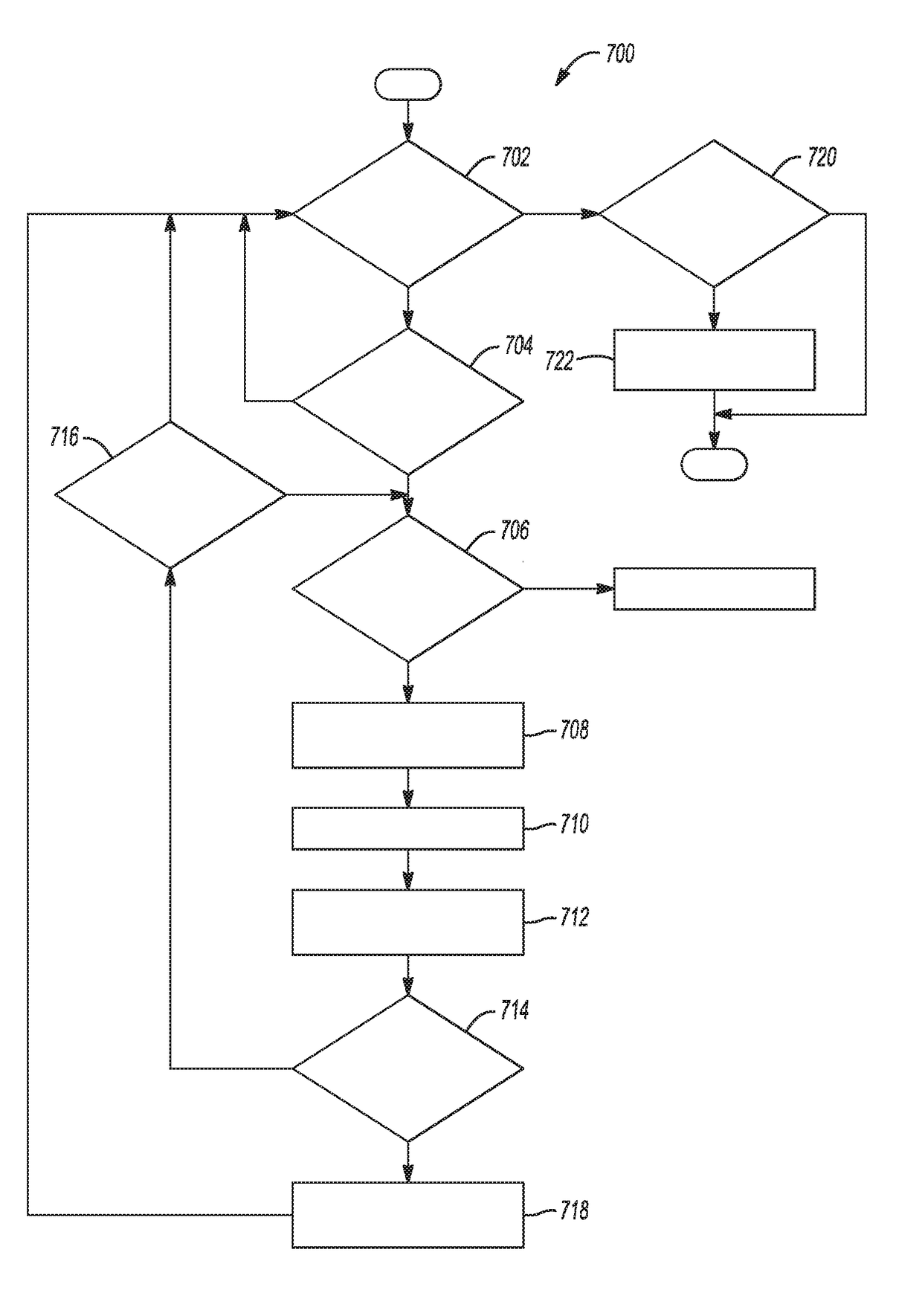
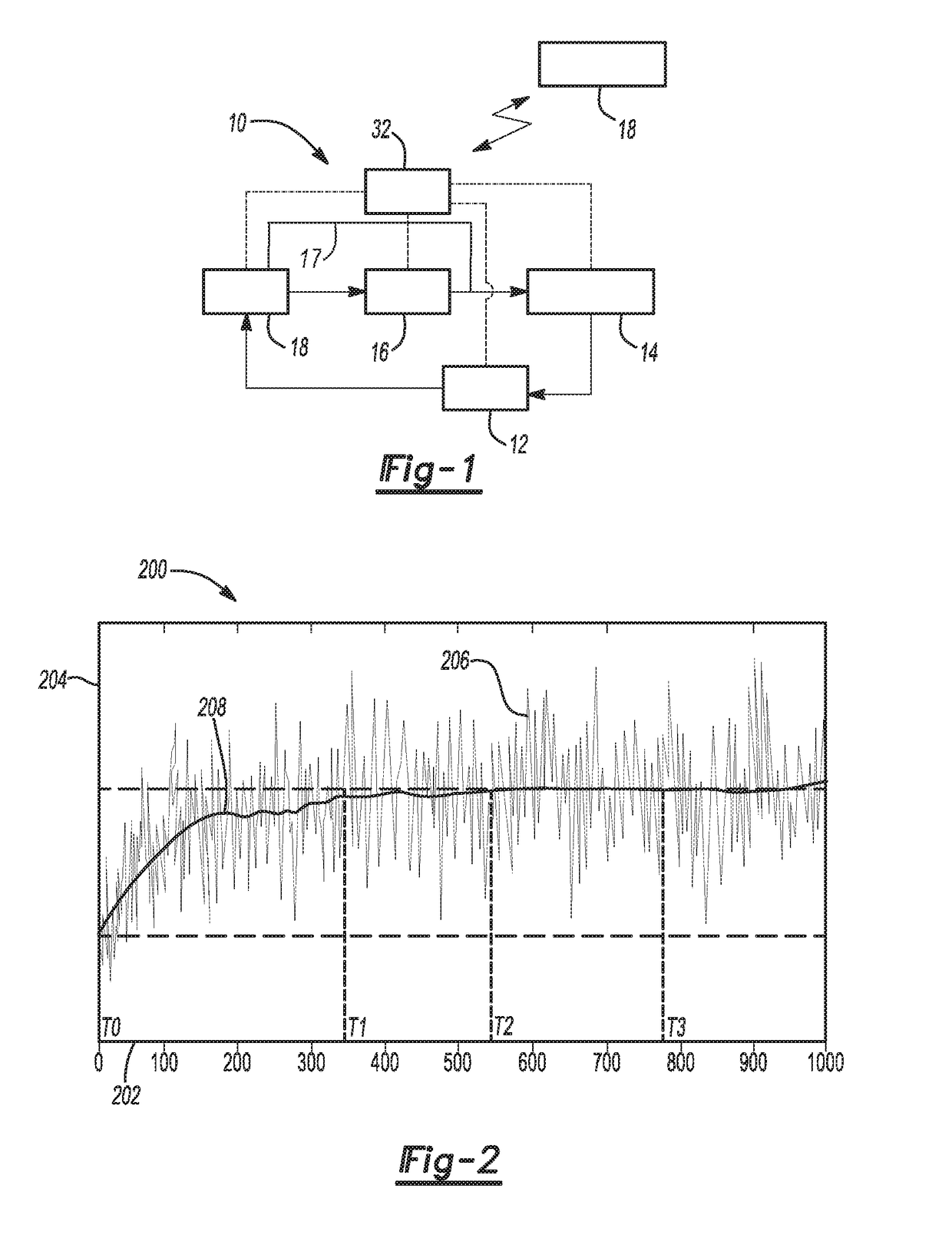
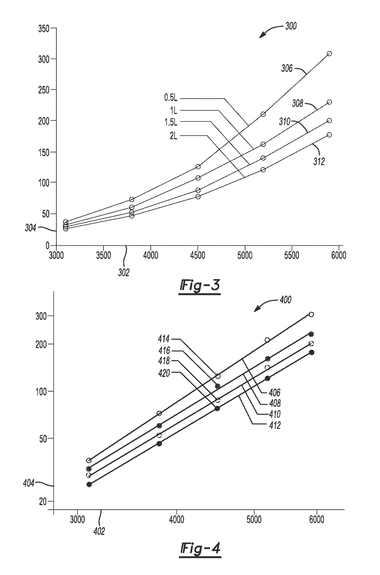
[0005]A system for detecting at least one of a coolant leak and a flow obstruction includes a controller programmed to store a baseline value for a coolant flow characteristic indicative of an initial volume of coolant and detect a speed characteristic and a power draw characteristic of an electrically-powered coolant pump. The controller is also programmed to store data indicative of pump operational speed and pump power draw over a predetermined learning time duration in response to detecting a steady state operational speed of the coolant pump. The controller is further programmed to estimate a real-time value for the coolant flow characteristic based on an operational relationship between pump speed and pump power and update the estimate in real-time based on new sensor data. The controller is further programmed to detect a reduction in a volume of coolant based on a change in the coolant flow characteristic from the baseline value.

Problems solved by technology

Internal combustion engines generate significant heat and commonly require thermal management.
Coolant volume loss from the fluid circuit as well as flow obstructions may reduce efficacy of the temperature management, and potentially cause damage to engine components due to overheating.

Method used


Image

  • Engine cooling systems and methods
  • Engine cooling systems and methods
  • Engine cooling systems and methods

Examples


Embodiment Construction

[0013]Embodiments of the present disclosure are described herein. It is to be understood, however, that the disclosed embodiments are merely examples and other embodiments can take various and alternative forms. The figures are not necessarily to scale; some features could be exaggerated or minimized to show details of particular components. Therefore, specific structural and functional details disclosed herein are not to be interpreted as limiting, but merely as a representative basis for teaching one skilled in the art to variously employ the present invention. As those of ordinary skill in the art will understand, various features illustrated and described with reference to any one of the figures can be combined with features illustrated in one or more other figures to produce embodiments that are not explicitly illustrated or described. The combinations of features illustrated provide representative embodiments for typical applications. Various combinations and modifications of ...


PUM


Abstract

An engine coolant system includes a variable-opening valve having a plurality of tubes in fluid flow communication with an engine block and a radiator. The coolant system also includes an electrically-powered pump arranged to cycle coolant through the radiator and the engine block to regulate an engine temperature. The coolant system further includes a controller programmed to store a baseline relationship between pump speed and pump power draw using a nonlinear scale. The controller is also programmed to detect a steady state operating condition of the pump, and identify an operational relationship between real-time pump speed and a pump power draw. The controller is further programmed to detect a coolant leak based on a deviation between the baseline relationship and the operational relationship.

Description

TECHNICAL FIELD[0001]The present disclosure relates to vehicle powertrain cooling systems.INTRODUCTION[0002]Internal combustion engines generate significant heat and commonly require thermal management. Liquid coolant within a closed fluid circuit may be cycled through a block portion of an engine and other vehicle accessories to dissipate heat and maintain engine temperature within a desirable range. Coolant volume loss from the fluid circuit as well as flow obstructions may reduce efficacy of the temperature management, and potentially cause damage to engine components due to overheating.SUMMARY[0003]An engine coolant system includes a variable-opening valve having a plurality of tubes in fluid flow communication with an engine block, a radiator and at least one vehicle accessory. The coolant system also includes an electrically-powered pump arranged to cycle coolant through the radiator and the engine block to regulate an engine temperature. The coolant system further includes a ...

Claims


Application Information

Patent Timeline
Patent Type & Authority Patents(United States)
IPC IPC(8): F01P5/12F01P3/02F01P7/16F01P7/14
CPCF01P5/12F01P3/02F01P7/165F01P2007/146F01P2031/18F01P2025/04F01P2025/08F01P2025/64F01P2023/08F01P3/20F01P7/14F01P11/14F01P7/164F01P2005/125
Inventor DUAN, SHIMINGKNIEPER, CHRISTOPHER H.
Owner GM GLOBAL TECH OPERATIONS LLC
Learn More