
Test system supporting simplified configuration for controlling test block concurrency

a test system and simplified configuration technology, applied in automated test systems, semiconductor/solid-state device testing/measurement, instruments, etc., can solve the problems of increasing the complexity of testing

Active Publication Date: 2018-08-14
TERADYNE
View PDF22 Cites 9 Cited by
  • Summary
  • Abstract
  • Description
  • Claims
  • Application Information

AI Technical Summary

Benefits of technology

[0032]The inventors have recognized and appreciated that, though concurrent testing provides advantages, it introduces complexity in programming and configuring a test system. The inventors also have recognized and appreciated that the complexity of developing test blocks for concurrent testing of multiple devices, each with multiple cores, has resulted in inefficient utilization of tester resources. Similarly, difficulties in configuring the test system to support concurrent testing of multiple cores within the same device, whether or not multiple devices are tested in parallel, has led to inefficient utilization of tester resources.

Problems solved by technology

As semiconductor devices have gotten more complex, the complexity of testing has also increased.
Though, some test blocks need to be executed at different times, either because cores within a device cannot concurrently operate independently or because a test system lacks sufficient resources to test all instances of the cores concurrently.

Method used


Image

  • Test system supporting simplified configuration for controlling test block concurrency
  • Test system supporting simplified configuration for controlling test block concurrency
  • Test system supporting simplified configuration for controlling test block concurrency

Examples


Embodiment Construction

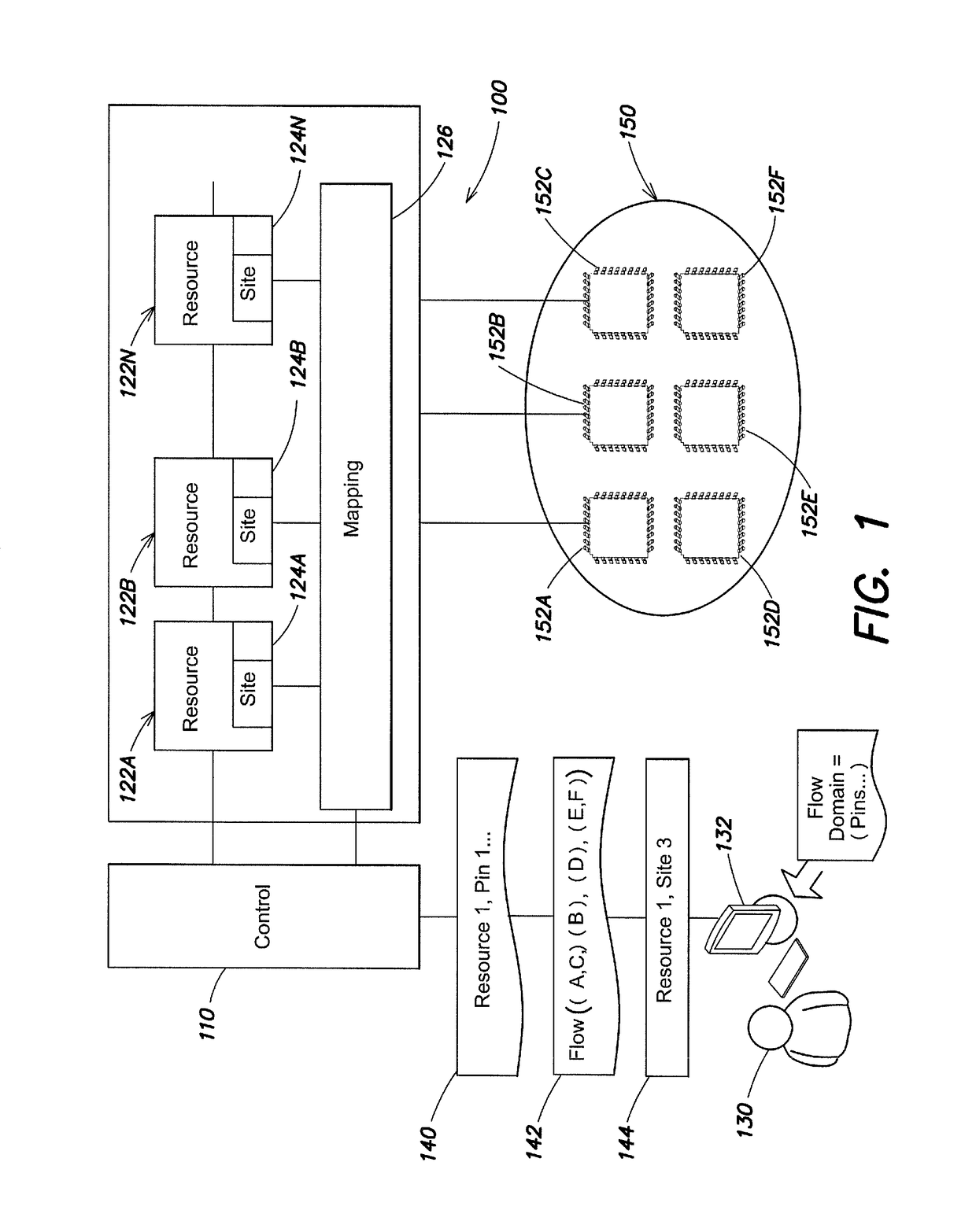
[0032]The inventors have recognized and appreciated that, though concurrent testing provides advantages, it introduces complexity in programming and configuring a test system. The inventors also have recognized and appreciated that the complexity of developing test blocks for concurrent testing of multiple devices, each with multiple cores, has resulted in inefficient utilization of tester resources. Similarly, difficulties in configuring the test system to support concurrent testing of multiple cores within the same device, whether or not multiple devices are tested in parallel, has led to inefficient utilization of tester resources.

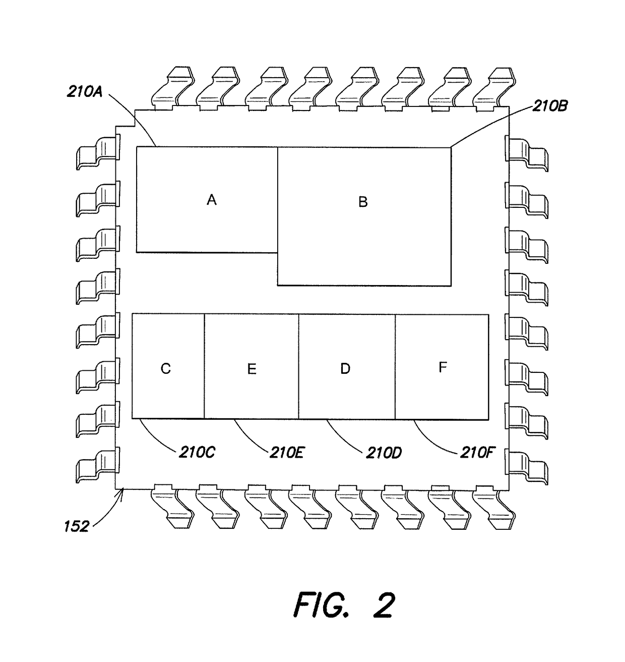
[0033]The inventors further have recognized and appreciated that more efficient usage of tester resources may be achieved by providing a test system with an ability to accept and apply user input indicating groups of pins associated with specific cores on a representative device under test. Here, a “core” may indicate a portion of a semiconductor device...


PUM


Abstract

Techniques for configuring a test system that enable simple specification of a degree of concurrency in testing separate functional portions of a semiconductor device. For a test flow with multiple sub-flows, the pins accessed in connection with each sub-flow may define a flow domain. Site regions, each associated with a flow domain, may be defined. Tester sites may be associated with each of these flow domain specific site regions and independently operating resources may be assigned to these tester sites. A second portion of the defined site regions may be associated with tester sites, but resources assigned to these site regions may be accessed from multiple flow domains. Test blocks, even if not developed for concurrent execution, may be executed concurrently using resources in the flow domain specific site regions. Flexibility is provided to share resources through the use of the second portion of the site regions.

Description

BACKGROUND[0001]Test systems are widely used to test semiconductor devices at multiple stages during their manufacture. A test system includes components, called resources, that can generate and measure signals that can establish and measure an operating state of a device under various conditions. A resource, for example, may be an arbitrary waveform generator that can be programmed to generate a waveform of a desired shape. Another type of resource may capture a sequence of samples of an analog signal. Yet another type of resources may generate or measure DC voltages or currents or digital signals. A test is executed by controlling the resources to generate and measure test signals at multiple test points of a device under test.[0002]Before executing a test, the test system is configured for the particular type of semiconductor device being tested. The test, in conjunction with the configuration information needed to configure the test system to execute the test, may be regarded as...

Claims


Application Information

Patent Timeline
Patent Type & Authority Patents(United States)
IPC IPC(8): H01L21/66G06F19/00G01R31/20G01R31/01G01R31/28
CPCG01R31/01H01L22/20G01R31/2834H01L2924/0002H01L2924/00
Inventor KING, JASON D.PYE, RICHARDSTIMSON, RANDALL B.SHIRK, STEVEN R.
Owner TERADYNE
Learn More