Connector

a technology of connectors and connectors, applied in the direction of coupling device connection, securing/insulating coupling contact members, electrical apparatus, etc., can solve the problems of poor tolerance insensitive, difficult connection of connectors with electrical components, stress generation, etc., and achieve enhanced tolerance insensitive of connectors

Active Publication Date: 2018-08-07
SHENZHEN SHENTAI WEIXIANG ELECTRONICS CO LTD
View PDF15 Cites 6 Cited by
  • Summary
  • Abstract
  • Description
  • Claims
  • Application Information

AI Technical Summary

Benefits of technology

[0006]In aforementioned connector of the embodiment, the first step is received in the latching groove of the first end, and the first conductive terminal resists the first contact sheet. When the first conductive terminal slides along the first direction on the first contact sheet, the first connecting member slides along the first direction relative to the second connecting member. The second step is received in the latching groove of the second end, and the second conductive terminal resists the second contact sheet. When the second conductive terminal slides along the second direction on the second contact sheet, the third connecting member slides along the second direction relative to the second connecting member. The third connecting member can slide along the third direction on the second case. Because the electrical components coupled to opposite ends of the connector can slide along three directions which are perpendicular to each other, i.e. deviations in the design of the structure of the electrical components on opposite ends of the connector are allowed, such that a problem of a difficulty of a connection between the connector and the electrical components which is caused by a deviation of the design of the structure of the electrical components can be avoided, thereby a tolerance insensitive of the connector is enhanced.

Problems solved by technology

When a design deviation of the electrical component emerges, the connector is difficult to connect with the electrical component.
At the time, even though the electrical component is connected to the connector, a relative greater stress is generated, and an electrical performance is greatly influenced, therefore, a tolerance insensitive is poor.

Method used


Image

  • Connector
  • Connector
  • Connector

Examples


Embodiment Construction

[0027]Embodiments of the invention are described more fully hereinafter with reference to the accompanying drawings, in which preferred embodiments of the connector are shown. The various embodiments of the connector may, however, be embodied in many different forms and should not be construed as limited to the embodiments set forth herein. Rather, these embodiments are provided so that this disclosure will be thorough and complete, and will fully convey the scope of the connector to those skilled in the art.

[0028]Unless otherwise defined, all terms used herein have the same meaning as commonly understood by one of ordinary skill in the art to which this invention belongs. Terms in the description of the connector are for the purpose of describing specific embodiments, and are not intend to limit the invention. As used herein, the term “and / or” includes any and all combinations of one or more of the associated listed items.

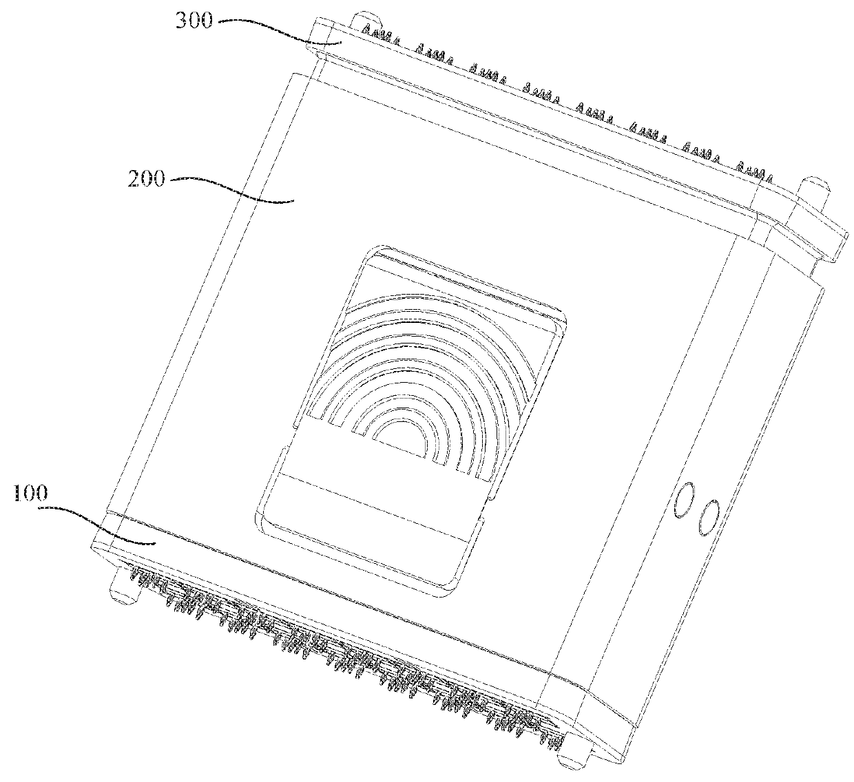
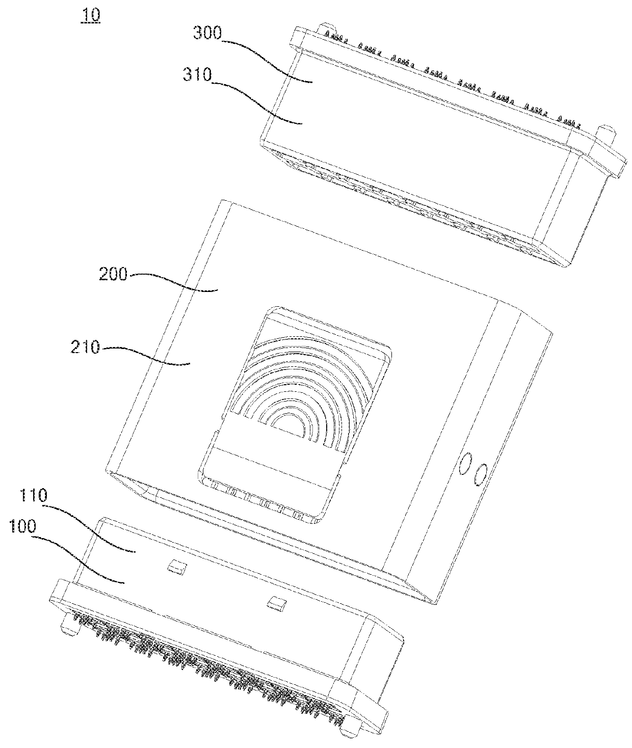
[0029]As shown in FIG. 1, a connector 10 according to an emb...


PUM


Abstract

The present invention relates to a connector. Aforementioned connector includes a first connecting member, a second connecting member, and a third connecting member. The first connecting member includes a first case, a first insulator, and a first conductive terminal, wherein the first case defines a first receiving chamber therein, the first insulator is received in the first receiving chamber, an external sidewall of the first case is provided with a first step. The second case defines a containing hole, the PCB board is received in the containing hole, a first end and a second end of the second case each defines a latching groove, the latching grooves is in communication with the containing hole. The third connecting member includes a third case, a second insulator, and a second conductive terminal, wherein the third case defines a second receiving chamber therein. In above connector, because the electrical components coupled to opposite ends of the connector can slide along three directions which are perpendicular to each other, such that a problem of a difficulty of a connection between the connector and the electrical components which is caused by a deviation of the design of the structure of the electrical components can be avoided, thereby a tolerance insensitive of the connector is enhanced.

Description

FIELD OF THE INVENTION[0001]The present invention relates to a technical field of electronic devices, and more particular relates to a connector.BACKGROUND OF THE INVENTION[0002]Connector is a commonly used component in communication equipment. Opposite ends of the common connector are connected to two electrical components respectively. When a design deviation of the electrical component emerges, the connector is difficult to connect with the electrical component. At the time, even though the electrical component is connected to the connector, a relative greater stress is generated, and an electrical performance is greatly influenced, therefore, a tolerance insensitive is poor.SUMMARY OF THE INVENTION[0003]Accordingly, it is necessary to provide a connector directed to solve a problem of a poor tolerance insensitive of the connector.[0004]A connector includes:[0005]a first connecting member including a first case, a first insulator, and a first conductive terminal, wherein the firs...

Claims


Application Information

Patent Timeline
Patent Type & Authority Patents(United States)
IPC IPC(8): H01R12/58H01R12/62
CPCH01R12/62H01R12/585H01R12/70H01R13/40H01R12/7082H01R12/721H01R12/732H01R12/91H01R13/518H01R12/00H01R12/51H01R13/629H01R31/06
Inventor WANG, JIANCHEN, PING
Owner SHENZHEN SHENTAI WEIXIANG ELECTRONICS CO LTD
Why Eureka
Try Eureka