
Switchable magnetic array

Active Publication Date: 2018-07-24
APPLE INC
View PDF30 Cites 6 Cited by
  • Summary
  • Abstract
  • Description
  • Claims
  • Application Information

AI Technical Summary

Benefits of technology

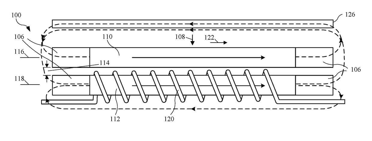
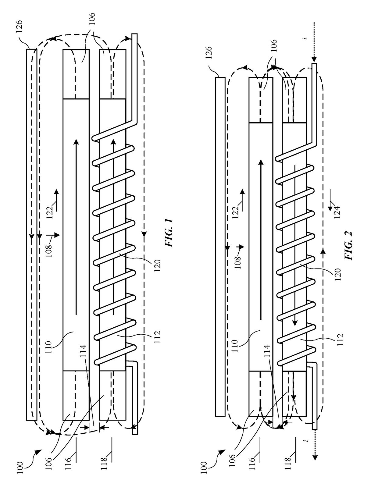
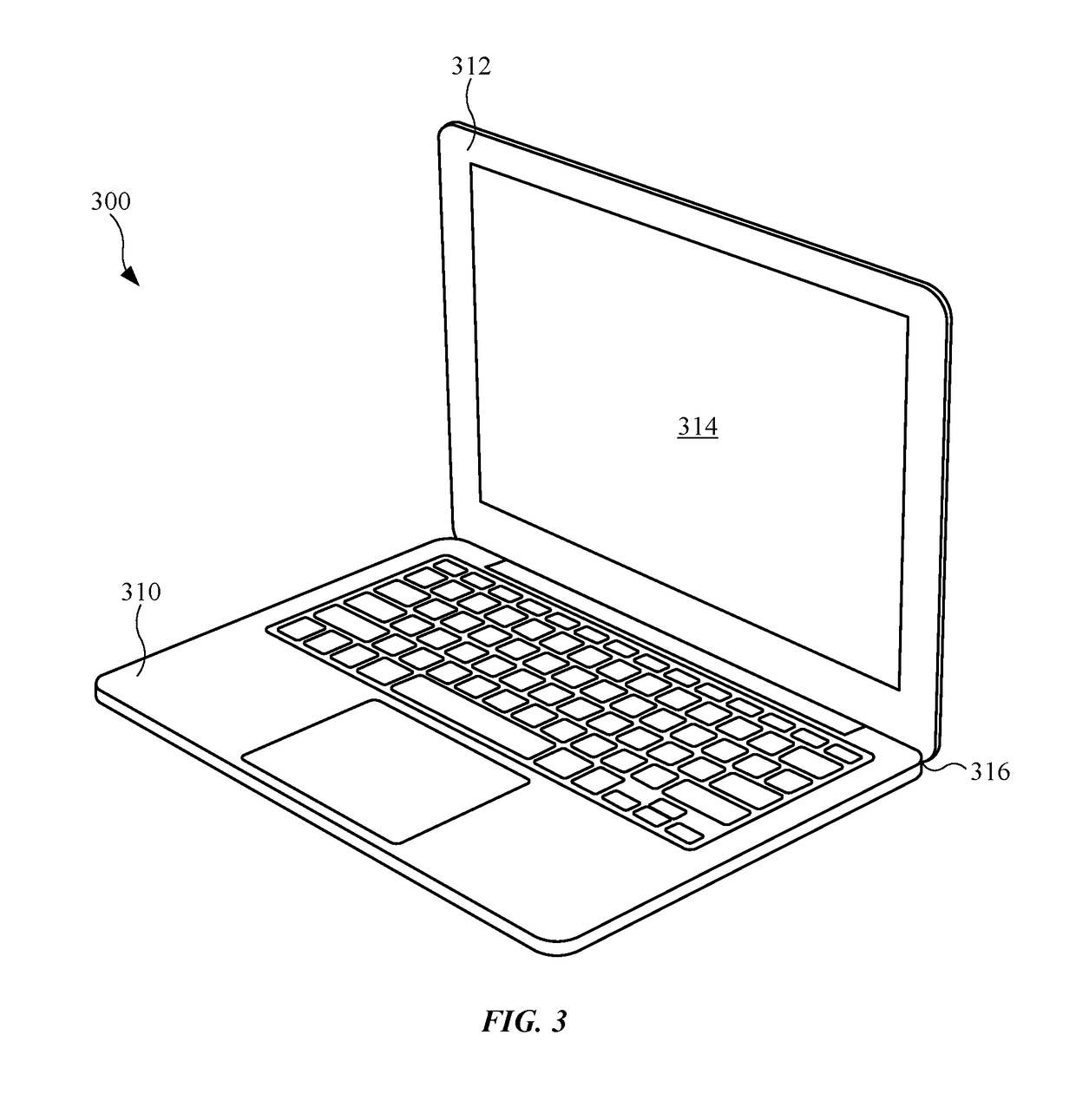
The patent describes an electronic device with a switchable magnet array that can be used to securely attach a lid to a base. The switchable magnet array includes a first magnetic layer, a second magnetic layer, and a gap between them. By applying a current pulse to a conductor, the direction of the second magnetic layer's magnetization can be reversed, creating an attractive force to latch the lid and base together. The switchable magnet array can be controlled using a drive circuit and a coil. The technical effects of this invention include improved security and ease of use for electronic devices.

Problems solved by technology

This may reduce the attractive force between the permanent magnets and the electromagnet, which may make the permanent magnets and the electromagnets less effective as a latch.
However, a larger remnant magnetization may increase the risk that the permanent magnets inadvertently damage components or devices that are sensitive to strong magnetic fields, such as credit cards.
Because it is typically difficult to reduce or turn off the magnetic field provided by permanent magnets, the use of permanent magnets as latches in laptops may be less desirable.
However, in practice, electromagnets consume considerable power and generate heat, neither of which is desirable in portable electronic devices such as laptops.

Method used


Image

  • Switchable magnetic array
  • Switchable magnetic array
  • Switchable magnetic array

Examples


Embodiment Construction

[0039]An electronic device (such as a laptop) may selectively latch a base to a lid using a switchable magnet array. In particular, a drive circuit in the electronic device may apply at least a current pulse to a conductor that generates a magnetic field to reverse a direction of a remnant magnetization in the switchable magnet array. By reversing the direction of the remnant magnetization, the electronic device may selectively increase or decrease a magnetic field generated by the switchable magnet array at an attraction plate in the electronic device. This magnetic field may, in turn, result in an attractive force between the switchable magnet array and the attraction plate, thereby selectively latching the base and the lid when the base and the lid are proximate to each other.

[0040]By allowing the magnetic field produced by the switchable magnet array to be selectively changed, this latching technique may provide a compact, low-power technique for latching components (such as the...


PUM


Abstract

An electronic device (such as a laptop) may selectively latch a base to a lid using a switchable magnet array. In particular, a drive circuit in the electronic device may apply at least a current pulse to a conductor that generates a magnetic field to reverse a direction of a remnant magnetization in the switchable magnet array. By reversing the direction of the remnant magnetization, the electronic device may selectively increase or decrease a magnetic field generated by the switchable magnet array at an attraction plate in the electronic device. This magnetic field may, in turn, result in an attractive force between the switchable magnet array and the attraction plate, thereby selectively latching the base and the lid when the base and the lid are proximate to each other.

Description

FIELD[0001]The following description relates to switchable magnet arrays, including a switchable magnetic array in an electronic device that selectively latches components in the electronic device.BACKGROUND[0002]Permanent magnets are often used as latches to mechanically couple components in devices. For example, permanent magnets can be included in a portable electronic device, such as a laptop computer (which is sometimes referred to as a ‘laptop’), to latch a lid to a base. In particular, permanent magnets may be included in the lid and the base. When the lid is proximate to the base, the permanent magnets may provide an attractive force that latches the lid to the base without consuming any power.[0003]However, as the form factor in laptops is decreased, there may be less room for the permanent magnets. Consequently, the area and / or the thickness of the permanent magnets may need to be decreased. This may reduce the attractive force between the permanent magnets and the electro...

Claims


Application Information

Patent Timeline
IPC IPC(8): H01H9/00G06F1/16H01F7/06H01F1/03
CPCG06F1/1679G06F1/1616H01F7/06H01F1/0306H01F7/0252H01F13/003
Inventor HAMEL, BRADLEY J.LIGTENBERG, CHRISTIAAN A.DIFONZO, JOHN C.GERY, JEAN-MARC
Owner APPLE INC
Learn More