Rolling bearing assembly

a technology of rolling bearings and components, which is applied in the direction of bearing components, bearing unit rigid support, shafts and bearings, etc., can solve the problems of loss of compatibility and change of range of manufacturers of mechanical systems and/or rolling bearings, so as to reduce time and design costs of mechanical systems, reduce size, and reduce the effect of siz

Active Publication Date: 2018-07-17
AB SKF
View PDF30 Cites 0 Cited by
  • Summary
  • Abstract
  • Description
  • Claims
  • Application Information

AI Technical Summary

Benefits of technology

[0010]It is to these problems that the invention is intended more particularly to respond, by providing a rolling bearing assembly that is simple to produce and to mount, and is modular in terms of its use and its adaptation to several applications.
[0014]A standard rolling bearing of reduced size can be adapted to further applications without the overall mechanical system having to be modified. This allows a reduction in time and the design costs of the mechanical system. In addition, if the dimensions of the housing are outside a predefined range, it is possible to adapt a standard rolling bearing to the range.
[0015]The invention also makes it possible to adapt a rolling bearing of reduced size instead of a rolling bearing with larger dimensions but incorporating additional functionalities by virtue of the flanges.
[0017]Furthermore, since the flanges of the two races are in sliding contact with one another, the rolling bearing can be sealed. It may then be unnecessary to provide sealing means inside the rolling bearing, such as lip seals mounted in one race and in sliding contact or forming a labyrinth with the other race. By contrast, the rolling bearing can be equipped with such sealing means in addition to the flanges so as to increase the sealing of the rolling bearing in particularly critical environments (pollution, water, dust, particles).
[0029]At least one flange provides at least one layer of electrically insulating material so as to prevent the passage of electric current through the rolling bearing.

Problems solved by technology

The conditions relating to torque, rotational speed, load, environment or even the available space in the housing have an effect on the rolling bearing and are thus design constraints therefor.
However, manufacturers of mechanical systems and / or rolling bearings can change their ranges and lose compatibility.

Method used


Image

  • Rolling bearing assembly
  • Rolling bearing assembly
  • Rolling bearing assembly

Examples


second embodiment

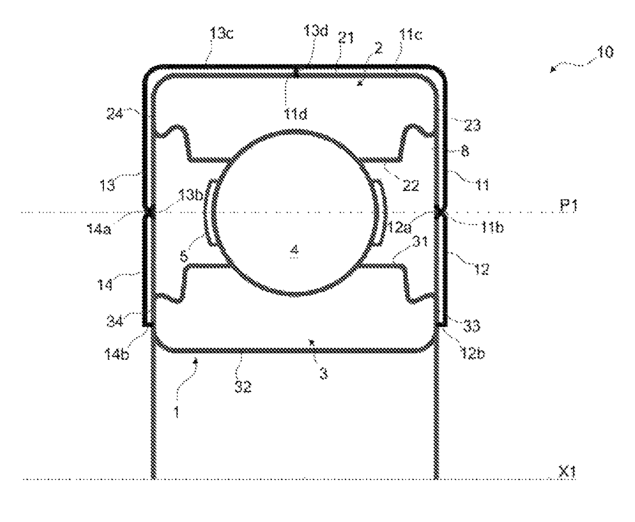
[0065]Alternatively, and which is illustrated in FIG. 3, the flanges 12 and 14 of the inner race 3 are also extended by axial portions 12c and 14c, respectively.

[0066]The axial portions 12c and 14c are annular and each cover a part of the bore 32 in the inner race 3 so as to entirely cover the surface 32. According to an alternative embodiment which is not shown, it is possible for the axial portions 12c and 14c not to be annular, the flanges 12 and 14 then being extended by a plurality of axial portions12c and 14c, respectively.

[0067]The axial portions 12c and 14c are connected securely together at their respective axial ends 12d and 14d.

[0068]By virtue of this second embodiment, the flanges 12 and 14 are both secured to the inner race 3 by cooperation of their respective axial portions 12c and 14c. It is then not necessary to fix the flanges 12 and 14 directly to the rolling bearing. The assembly made up of the flanges 12 and 14 with their respective axial portions 12c and 14c d...

fourth embodiment

[0077]By virtue of this fourth embodiment, the contact between two lips 11e, 12e and / or 13e, 14e is preserved even if there is misalignment of the rolling bearing 1 during mounting or use.

[0078]According to embodiments that are not shown, the rolling bearing can be provided with one or more rows of rolling elements. The rolling elements can be balls, rollers, needles or any other type of rolling element. By contrast, it is possible for the rolling bearing not to be provided with rolling elements and to consist of a plain bearing.

[0079]According to embodiments that are not shown, at least one flange provides at least one layer of material made of vibration damping material and / or at least one flange provides at least one layer of electrically insulating material so as to prevent the passage of electric current through the rolling bearing.

[0080]The technical features of the embodiments and variants that are envisaged above can be combined with one another.


PUM


Abstract

A rolling bearing assembly including a rolling bearing provided with a first race having a bore, two front edges and an outer cylindrical surface, and with a second race provided with a bore, two front edges and an outer cylindrical surface. The first and second races rotate relatively about a central axis. The assembly is intended to be mounted in a housing. The assembly provides at least one first annular flange that is secured to the first race and at least partially covers a front edge of the first race, and at least one second annular flange that is secured to the second race and at least partially covers a front edge of the second race. Free ends of the first and second annular flanges are in sliding contact. The difference in dimensions between the housing and the rolling bearing is compensated by the flanges.

Description

CROSS REFERENCE TO RELATED APPLICATIONS[0001]This application claims priority to French patent application no. 1557243 filed on Jul. 29, 2015, the contents of which are fully incorporated herein by reference.FIELD OF THE INVENTION[0002]The present invention relates to an assembly comprising a rolling bearing.[0003]A rolling bearing generally provides an inner race and an outer race, the races being in relative rotation with respect to one another. Between one another, the races can define a bearing chamber in which the rolling elements, such as balls, needles, rollers, are housed.BACKGROUND OF THE INVENTION[0004]A rolling bearing is intended to be mounted in a housing of a mechanical system, between a fixed mechanical element and a rotary mechanical element so as to support the relative rotation thereof.[0005]The design of a rolling bearing, more specifically the type of rolling bearing, the number of rows of rolling elements, the type of rolling elements, the size of the races and ...

Claims


Application Information

Patent Timeline
Patent Type & Authority Patents(United States)
IPC IPC(8): F16C33/76F16C35/073F16C19/06F16C33/78F16C35/077
CPCF16C33/767F16C19/06F16C33/782F16C35/073F16C35/077F16C33/7886F16C33/783F16C33/7806F16C33/7823
Inventor BERENS, FRANK
Owner AB SKF
Why Eureka
Try Eureka