
Mechanical timepiece fitted with a device for adjusting the shake of a rotating part or wheel set

A technology of rotating parts and adjusting devices, which is applied to mechanically driven clocks, frequency-adjusting mechanisms, clocks and other directions, and can solve the problems of complex adjustment systems and restricting the arrangement of the balance rod.

Active Publication Date: 2007-07-04
OMEGA SA
View PDF1 Cites 14 Cited by
  • Summary
  • Abstract
  • Description
  • Claims
  • Application Information

AI Technical Summary

Problems solved by technology

Therefore, this adjustment system is relatively complex and limits the possibilities of arranging the balance lever in the timepiece movement

Method used


Image

  • Mechanical timepiece fitted with a device for adjusting the shake of a rotating part or wheel set
  • Mechanical timepiece fitted with a device for adjusting the shake of a rotating part or wheel set
  • Mechanical timepiece fitted with a device for adjusting the shake of a rotating part or wheel set

Examples


Embodiment Construction

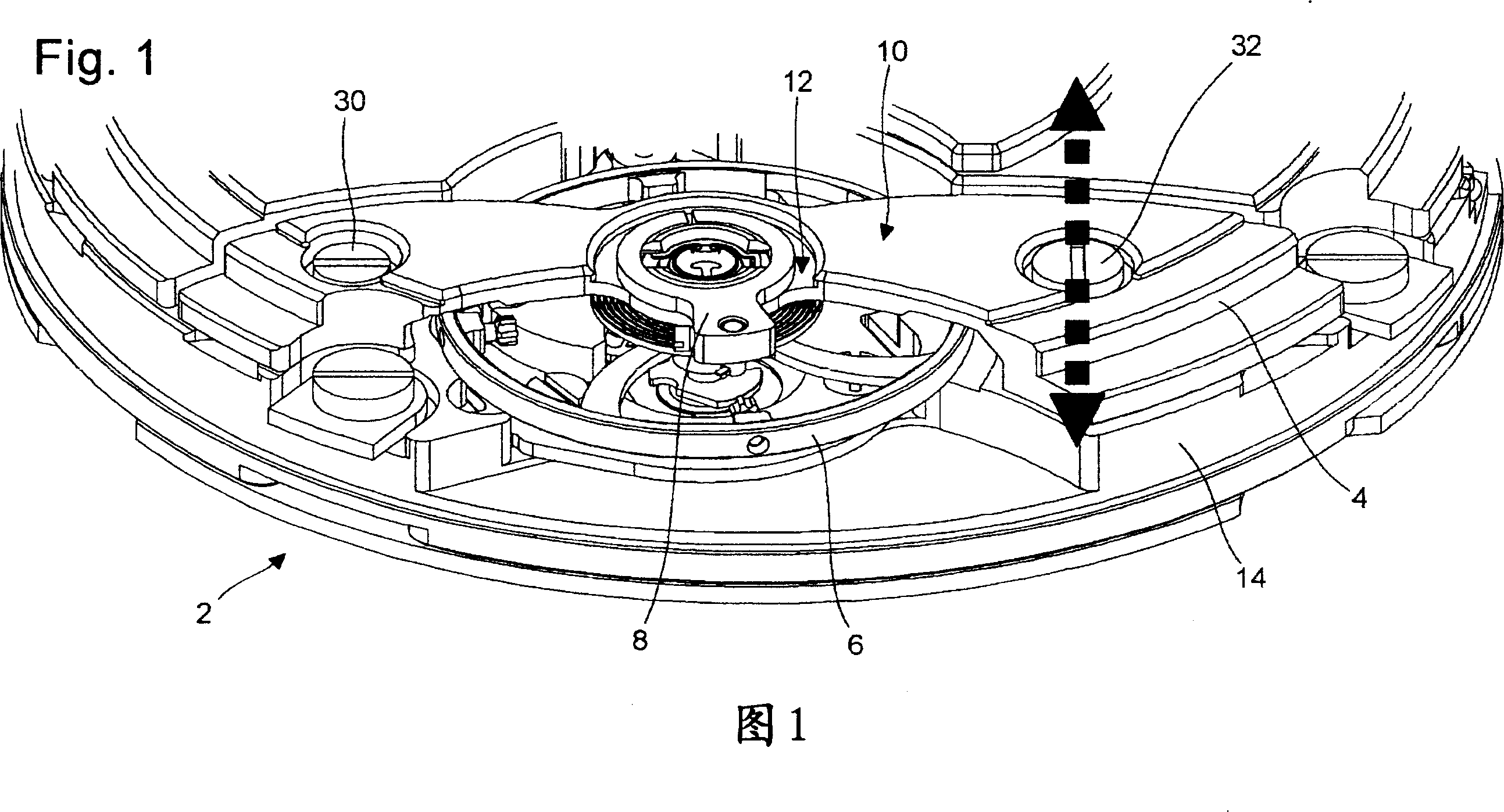
[0016] FIG. 1 shows a mechanical timepiece 2 equipped with a rotating part and comprising a device according to the invention for regulating the oscillation of this moving part.

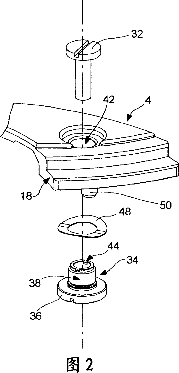
[0017] A preferred embodiment of the present invention will be described below with reference to FIGS. 2 to 5. FIG. The lever in this embodiment is the balance lever 4 and the rotating part is the balance 6 . Balance 6 comprises, in a conventional manner, a shaft or arbor pivoting at one end in a first bearing supported by plate 10 of the balance lever. Said first bearing is arranged in the bore of the balance spring stud holder 8 with a shock absorber arrangement known to those skilled in the art. The balance spring stud holder 8 rests on the central seat 12 of the stem 4 . The second end of the balance shaft pivots in a second bearing arranged in the plate 14 of the timepiece 2 .

[0018] Balance lever 4 is a double lever formed by two bases 16 and 18 arranged respectively on either side of plat...


PUM


Abstract

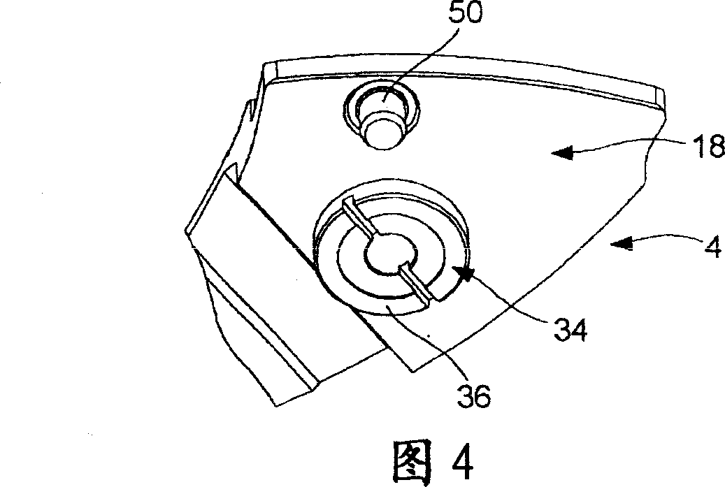
The timepiece includes means for adjusting the shake of a rotating part or wheel set, in particular a balance one bearing of which is arranged in a bar ( 4 ). This bar comprises a base ( 18 ) associated with a adjusting screw ( 34 ) one end ( 36 ) of which rests on the bottom plate. Rotating this adjusting screw varies the distance between the base and the bottom plate ( 14 ). The centre of the adjusting screw is pierced for the passage of a tightening screw ( 32 ) for fixing the bar to the bottom plate. This adjusting screw is arranged in a hole ( 42 ) passing through the base ( 18 ) and can be rotated through the hole from the top face ( 46 ) of the bar in order to adjust the balance shake.

Description

technical field [0001] The invention relates to a mechanical timepiece equipped with a device for regulating the oscillation of a rotating part or of a wheel set, in particular of a balance wheel. Background technique [0002] The ends of a balance lever, balance shaft or arbor associated with means for adjusting the relative position of two bearings are known from Swiss Patent No. 20552 filed on 1 November 1899 in the name of J.L. Kurtz respectively pivot in said bearings. The balance lever described is of the simple type, that is, with a single base, fixed to a plate, and a plate, which is connected to one end of the single base and has at its other free end for Arrange the bores for the bearings. The balance lever is secured to the plate by a single screw that runs right through this single base. [0003] In this patent, the swing of the balance shaft is adjusted by adjusting the height of the balance wheel lever plate. For this purpose, three adjusting screws are arr...

Claims


Application Information

Patent Timeline
Patent Type & Authority Applications(China)
IPC IPC(8): G04B18/04
CPCG04B29/022G04B31/00G04B35/00G04B17/285
Inventor C·鲁费纳赫特I·维拉
Owner OMEGA SA
Learn More