
A cardiac surgery aid

A technology of cardiac surgery and assistive devices, applied in the field of cardiac surgical assistive devices, can solve problems such as small adjustment range, easy injury to patient's ribs, patient injury, etc., and achieve the effect of strong adaptability and convenient operation

Active Publication Date: 2021-05-25
吕振乾 +1
View PDF0 Cites 0 Cited by
  • Summary
  • Abstract
  • Description
  • Claims
  • Application Information

AI Technical Summary

Problems solved by technology

It solves the technical problem that the two head ends of the chest opener in the prior art are easy to injure the patient's ribs, but the above chest opener can only be adjusted from one side, but since the chest cavity is symmetrical, if it is only adjusted from one side On the one hand, the adjustment range is small; on the other hand, the symmetry of the thoracic opening cannot be guaranteed, which is inconvenient for medical staff to operate, and it is easy to cause damage to the patient

Method used


Image

  • A cardiac surgery aid
  • A cardiac surgery aid
  • A cardiac surgery aid

Examples


Embodiment 1

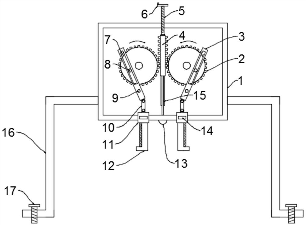
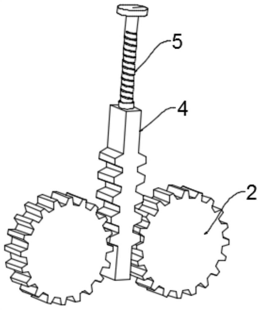
[0024] see Figure 1~2 , in an embodiment of the present invention, a heart surgery assisting device includes a mounting frame 1 and a spreader assembly, the spreader assembly includes two spreader plates 12 and is used to drive the two spreader plates 12 to move in reverse synchronously The drive unit, the two expansion plates 12 are respectively fixedly installed on the two mounting blocks 11 at the bottom of the mounting frame 1, the mounting blocks 11 are slidably connected with the mounting frame 1, and the mounting block 11 is integrally provided with a slider 14, The mounting frame 1 is provided with a chute for the sliding block 14 to slide. The driving unit includes a gear 2, a rack 4, a threaded rod 5, a driving rod 3 and a connecting rod 10, and the threaded rod 5 passes through the installation The top of the frame 1 is threadedly connected with the top of the mounting frame 1, the top of the threaded rod 5 is fixed with a turntable 6, the turntable 6 is preferably...

Embodiment 2

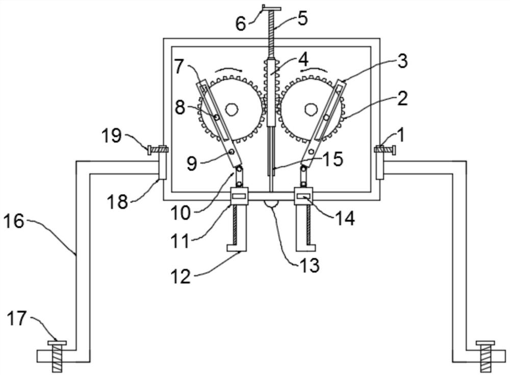
[0028] see Figure 3-4 The difference between the embodiment of the present invention and embodiment 1 is that the installation rod 16 is slidingly connected with the installation frame 1, and a slide rail 18 is installed on the installation rod 16 through screws, and the installation frame 1 is provided with a sliding block 14 slidingly connected chute, the first fastening bolt 19 is connected between the slide rail 18 and the mounting frame 1, so that the height of the mounting frame 1 can be adjusted according to the body shape of the patient, and the adaptability is strong;

[0029] Further, in order to be able to adjust the maximum stroke of the expansion plate 12 to meet different surgical needs, the cylindrical pin 8 is slidably installed on the gear 2, and the gear 2 is provided with a movable block 21 integrated with the cylindrical pin 8 , the gear 2 is provided with a guide groove for the movement of the cylindrical pin 8, and the second fastening bolt 20 for fixing...


PUM


Abstract

The invention discloses an auxiliary device for cardiac surgery, which includes a mounting frame and a spreading assembly, and the spreading assembly includes two spreading plates and a drive unit for driving the two spreading plates to move synchronously and reversely. The expansion plates are respectively fixedly installed on two mounting blocks at the bottom of the mounting frame, and the mounting blocks are slidably connected with the mounting frame. The driving unit includes a gear, a rack, a threaded rod, a driving rod and a connecting rod. On the gear, the application is equipped with a stretching component, which drives the threaded rod to rotate and move downward at the same time, the threaded rod drives the rack to move downward, the rack drives the two gears to rotate synchronously, and the two gears drive the drive rod to swing and drive The rod drives the installation block and the expansion plate at the bottom end to move outward through the connecting rod, so as to expand the chest cavity of the surgical patient, which is convenient for the medical staff to perform the operation. By adjusting the position of the cylindrical pin, the effect of adjusting the swing range of the driving rod can be achieved, thereby adjusting The movement stroke of the expansion board has strong adaptability.

Description

technical field [0001] The invention relates to the technical field of surgical auxiliary equipment, in particular to an auxiliary device for cardiac surgery. Background technique [0002] Cardiothoracic surgery also includes diseases of cardiac surgery and general thoracic surgery. Cardiovascular surgery studies heart and great vessel trauma, pericardial disease, congenital heart disease, acquired heart valve disease, ischemic heart disease, heart tumor, great vessel disease, intervention Sexual therapy techniques, surgical treatment of cardiac arrhythmias, cardiac pacing and implantable defibrillator, dynamic cardiomyoplasty, heart, lung and heart-lung transplantation, etc. [0003] Cardiac surgery requires the patient's chest to be opened for surgery. In the past, the patient needed physiological breathing and the chest was in a state of continuous contraction, which affected the medical staff's surgical operations. Therefore, a device was required. A Chinese utility mode...

Claims


Application Information

Patent Timeline
Patent Type & Authority Patents(China)
IPC IPC(8): A61B17/02A61G13/10A61B90/30
CPCA61B17/02A61G13/10A61B90/30A61B2090/309
Inventor 吕振乾
Owner 吕振乾
Learn More