
Digital data recording device and recording method

A technology for digital data and recording devices, applied in data recording, digital recording/reproduction, recording signal processing, etc., can solve the problem of reducing buffer memory capacity, increasing the area that cannot be used for recording, and reducing the actual usable area of ​​the disc, etc. problems, to achieve the effect of prolonging the recording time and reproduction time, and reducing the number of positioning times

Inactive Publication Date: 2007-06-27
SONY CORP
View PDF1 Cites 0 Cited by
  • Summary
  • Abstract
  • Description
  • Claims
  • Application Information

AI Technical Summary

Problems solved by technology

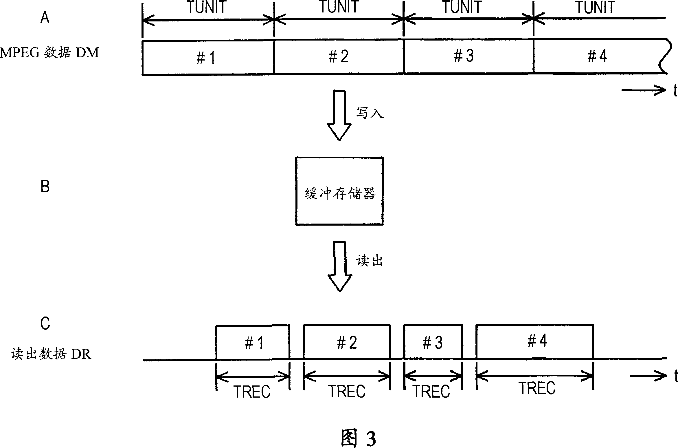
[0025] However, at, for example, time point t6, since the data amount of data #4 in the buffer memory is less than the data amount of one unit period TUNIT, the total amount of data of data #4 is unclear.
[0028] As a result, as shown at time point t6, if the data volume of the buffer memory DBUF is less than one unit period and the state of the data volume of TUNIT repeatedly occurs, the area that cannot be used for recording will increase, and the actual usable area on the disc will decrease.
[0031] However, in this method, for example, the data amount DBUF of the buffer memory at the time point t6 may be approximately equal to the maximum value of the data amount of TUNIT in one unit period depending on the situation, and when the data transfer rate (data rate) of the MPEG data is high When , since the data amount DBUF can vary within a range between a value close to the maximum value of the data amount of TUNIT in one unit period and the upper limit value DLIM, it is obvious that the capacity of the buffer memory becomes smaller

Method used


Image

  • Digital data recording device and recording method
  • Digital data recording device and recording method
  • Digital data recording device and recording method

Examples


Embodiment Construction

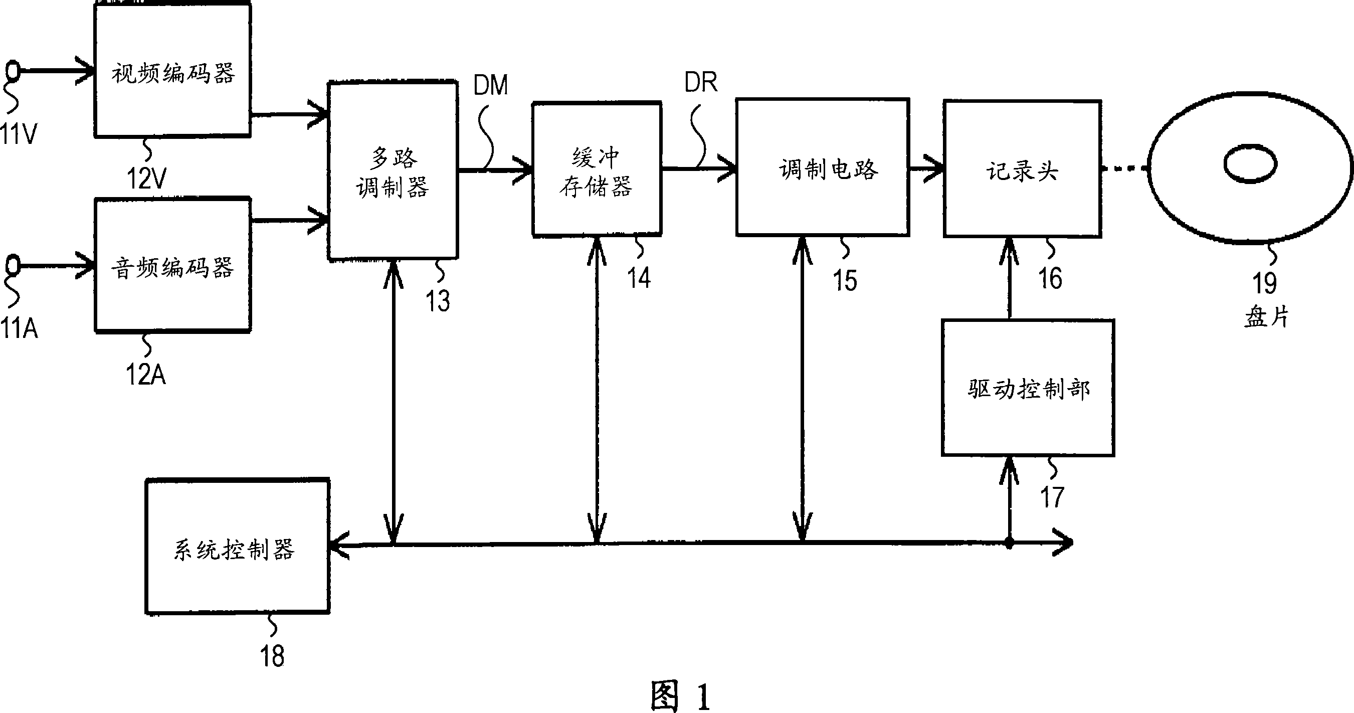
[0071] FIG. 1 shows an example of a recording device according to the present invention. The digital video signal and the digital audio signal are supplied to the video encoder 12V and the audio encoder 12A through the input terminals 11V and 11A, and are encoded into digital data (elementary stream) in MPEG2 format, for example. And, this encoded output is supplied to multiplexer 13, and multiplexed into a digital data (program stream) DM in MPEG2 format, for example as shown in FIG.

[0072] For example, as shown in FIG. 4A, the MPEG data DM is sequentially written into the buffer memory 14, and at the same time, sequentially read as data DR, and the read data DR is provided to the modulation circuit 15, and modulated for recording as a record. Signal. As shown in FIG. 4B, the recording signal is supplied to the recording head 16, and recorded on, for example, the disk 19.

[0073] Furthermore, in order to realize the above processing, a drive control unit 17 is provided, ...


PUM


Abstract

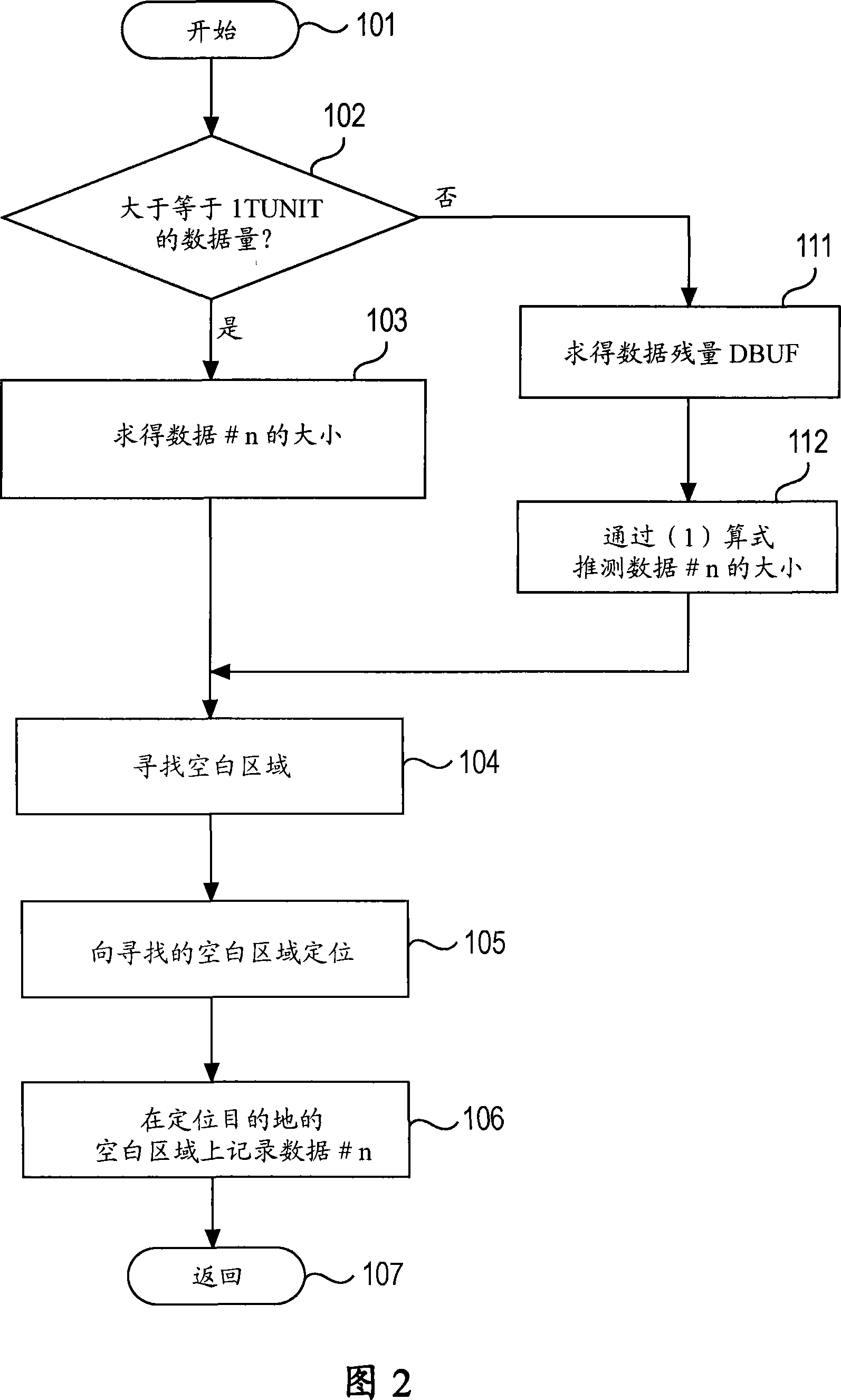
When dividing digital data of variable bit rate into continuous areas of unit periods, it is possible to suppress generation of fragmentation. When the data amount of the buffer memory is equal to or above the unit period, the digital data is read out from the buffer memory by the unit period and the digital data which has been read out is recorded as a continuous area (step 106). When the data amount of the buffer memory is smaller than the unit period, the data amount is predicted from the time corresponding to the digital data amount smaller than the unit period and from the length of the unit period (step 112). The digital data of the unit period is recorded in a recording-enabled area capable of continuously recording the digital data of the predicted data amount (step 106).

Description

technical field [0001] The invention relates to a digital data recording device and recording method. Background technique [0002] In a minidisc (registered trademark) used for recording and reproducing digital audio data, a predetermined amount of digital data constitutes a cluster, and this cluster serves as a unit for recording on a disc. [0003] Such a system is considered to be a system in which a period of about 10 to 20 seconds is regarded as a unit, and digital data of the unit period is recorded so as to occupy a continuous area on the disc. [0004] 3 is a diagram for explaining the signal processing method of such a system. For example, as shown in FIG. 3A, video signals and audio signals are encoded into digital data (program stream) DM in MPEG2 (Motion Picture Experts Group Phase 2) format. For example, as shown in FIG. 3B, this data DM is sequentially written in the buffer memory, and at the same time, as shown in FIG. 3C, it is sequentially read intermitten...

Claims


Application Information

Patent Timeline
Patent Type & Authority Applications(China)
IPC IPC(8): G11B20/10
CPCG11B20/10527G11B19/04G11B2020/1062
Inventor 山田诚佐藤孝幸小幡英生田所英司长尾吉人下野浩
Owner SONY CORP
Learn More