
Gene chip sample applying nozzle

A gene chip and spotting technology, applied in printing and other directions, can solve the problems of cleaning, drying, difficult sample loading, high manufacturing cost, complicated process, etc., and achieve the effects of easy cleaning and drying, low cost, and easy manufacturing.

Inactive Publication Date: 2007-06-27
章维一 +2
View PDF0 Cites 10 Cited by
  • Summary
  • Abstract
  • Description
  • Claims
  • Application Information

AI Technical Summary

Problems solved by technology

The above two types of spotting nozzles are all manufactured by micro-machining methods, the process is complicated, and the manufacturing cost is high; there is the possibility of being blocked by air bubbles and particles; cleaning, drying, and sample loading are difficult; the droplet volume is generally 0.1 to 0.4× 10 -9 Liter, the corresponding droplet diameter is usually 60 ~ 90μm

Method used


Image

  • Gene chip sample applying nozzle
  • Gene chip sample applying nozzle
  • Gene chip sample applying nozzle

Examples


Embodiment Construction

[0016] The present invention will be further described in detail below in conjunction with the drawings and specific embodiments:

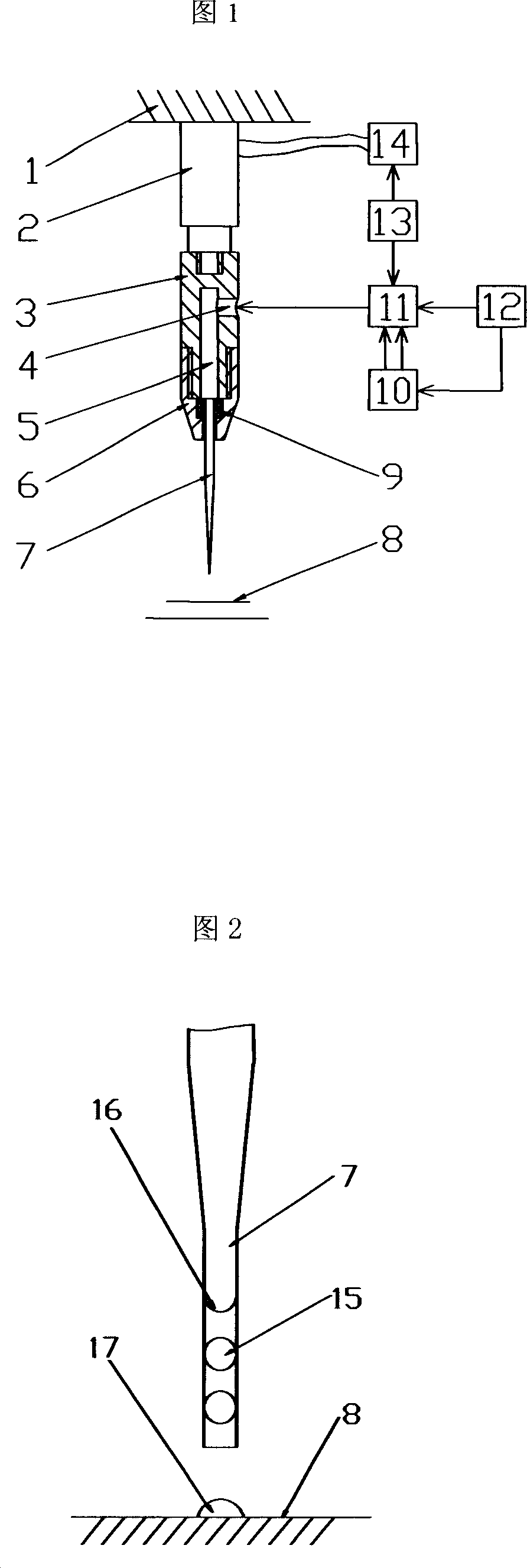
[0017] In FIG. 1, the gene chip spotting nozzle is mainly composed of a micro nozzle 7, a clamping and fixing device, a piezoelectric ceramic driver 2, a driving power source 14, a control valve 11, and a control computer 13. The fixed body 3, the sealing element 9, and the screw cap 6 constitute a clamping and fixing device. The large end of the micro nozzle 7 is matched with the sealing element 9 and placed in the cavity of the screw cap 6. The screw cap 6 is connected with the external thread at one end of the fixed body 3 through an internal thread. The elastic deformation of the sealing element 9 makes the micro nozzle 7 is tightly fixed on the longitudinal axis of the spotting nozzle. The other end of the fixed body 3 is rigidly connected to the external thread of one end of the piezoelectric ceramic driver 2 through an internal thread, and the ...


PUM


Abstract

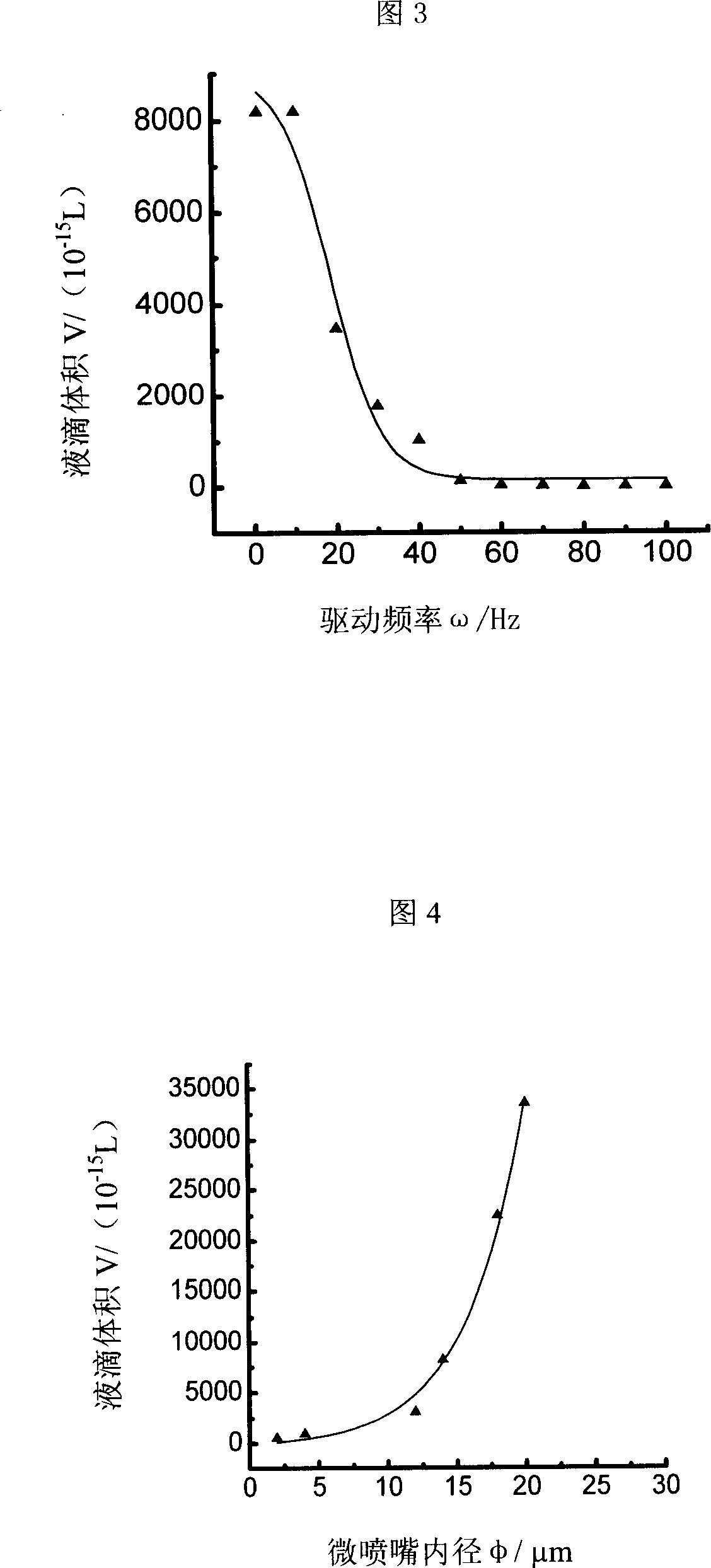
The gene chip sample applying nozzle includes a micro nozzle, a holding fixture, a piezoelectric ceramic driver, a driving power source, a control valve and a control computer. The micro nozzle is connected to one end of the piezoelectric ceramic driver directly by means of the holding fixture, and the other end of the piezoelectric ceramic driver is connected to the instrument. The present invention has simple structure and easy manufacture, and may be used to obtain micro liquid drop of volume in 10<-15>-10<-12> liter for making high density gene chip micro array.

Description

Technical field [0001] The invention relates to a gene chip spotting device, which includes a micro nozzle, a clamping and fixing device, a piezoelectric ceramic driver, a driving power supply, a control valve and a control computer. Background technique [0002] In the current prior art, there are mainly two types of nozzles for spotting gene chips. One is a nozzle that uses the principle of inkjet printing; the other is a piezoelectric-driven micropump, typically made by GeSiM, Germany. The microfluidic piezoelectric pipetting device, 2003 Vol. 3 No. 1 "Lab on a Chip" magazine reported the structure of the device in the article "Profile. The development of integrated microfluidic systems at GeSiM". The device is on a silicon chip. The piezoelectric crystal is pasted on one side, and the pump cavity and micro nozzle are processed by etching technology and the glass is anodic bonded as the cover. When a voltage pulse is applied to the piezoelectric crystal, the piezoelectric crys...

Claims


Application Information

Patent Timeline
IPC IPC(8): B41J2/135B41J2/16B41J2/01
Inventor 章维一侯丽雅房汝建
Owner 章维一
Learn More