Monopulse radar apparatus and antenna switch
A monopulse radar and switch technology, which is applied in the directions of antenna arrays, antennas, and measurement devices that are powered on separately, and can solve problems such as loss of meaning and increased processing time.
- Summary
- Abstract
- Description
- Claims
- Application Information
AI Technical Summary
Problems solved by technology
Method used
Image


Examples
Embodiment approach 1
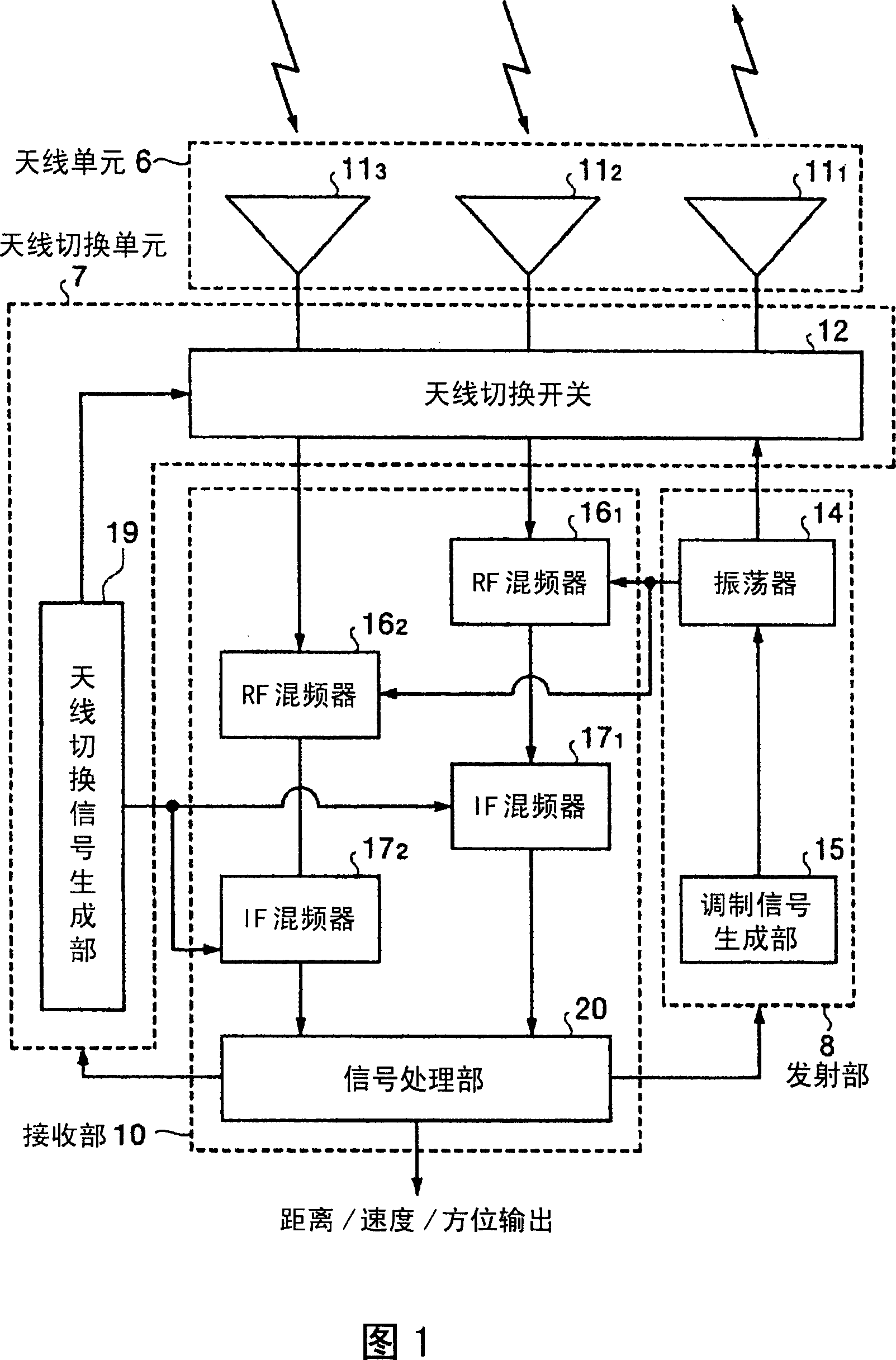
[0073] FIG. 1 is a block diagram showing the configuration of a monopulse radar device according to the present invention. Here, the radar device shown in FIG. 1 represents the configuration of a general monopulse radar device. On the other hand, the monopulse radar device of the present invention is characterized by the configuration of the transmitting and receiving antenna of the antenna unit, the configuration of the antenna switching unit, and the processing of the signal processing unit based on these configurations, which will be described in detail below. However, in describing the present invention, it is necessary to understand the configuration of a general monopulse radar device. Therefore, first, the configuration and the like of a monopulse radar device to which the present invention is applied will be described.
[0074] The monopulse radar device shown in FIG. 1 is composed of each processing unit whose processing function is divided into large blocks, that is, ...
Embodiment approach 2
[0091] FIG. 7 is a diagram showing detection areas where the center directions of the array antenna A and the array antenna B shown in FIG. 6 are shifted left and right, respectively. In Embodiment 1, the center directions of array antenna A and array antenna B are directed in the same direction, but Embodiment 2 is characterized in that the center directions of array antenna A and array antenna B are respectively shifted left and right. In addition, the configuration of each processing unit including the antenna unit in this embodiment is the same as that in the first embodiment.
[0092] Next, the single pulse processing of this embodiment will be described. In FIG. 7 , first consider a case where any one of array antenna A, array antenna B, and array antenna C performs transmission, and array antenna A and array antenna B perform monopulse processing. In this case, it is possible to detect the azimuth of an object present in the detection area R2 near the center of the are...
Embodiment approach 3
[0099] FIG. 8 is a diagram showing an antenna configuration of an antenna unit according to Embodiment 3. FIG. In the antenna unit of this embodiment, in the planar array antenna of Embodiment 1 or Embodiment 2, antenna elements are arranged such that the interval between the second antenna element group and the third antenna element group from the left is slightly enlarged. On the other hand, each array antenna is configured by using four antenna elements in the elevation direction as an antenna element group to form three array antennas, array antenna D, array antenna E, and array antenna F, in which two antenna element groups are combined. The configuration of each of these antennas is different from the configuration of Embodiment 1. The array antenna F is composed of the first and second antenna element groups from the left, and the array antenna E is composed of the third and fourth antenna element groups from the left. , the array antenna F consists of the fifth and six...
PUM
 Abstract
Description
Claims
Application Information
 - R&D
- Intellectual Property
- Life Sciences
- Materials
- Tech Scout
- Unparalleled Data Quality
- Higher Quality Content
- 60% Fewer Hallucinations
Browse by: Latest US Patents, China's latest patents, Technical Efficacy Thesaurus, Application Domain, Technology Topic, Popular Technical Reports.
© 2025 PatSnap. All rights reserved.Legal|Privacy policy|Modern Slavery Act Transparency Statement|Sitemap|About US| Contact US: help@patsnap.com