Camera system having image shake correction function
A shake correction and camera technology, applied in the field of camera systems, can solve problems such as increased cost, difficult shake correction functions for users, and complex communication and control
- Summary
- Abstract
- Description
- Claims
- Application Information
AI Technical Summary
Problems solved by technology
Method used
Image

Examples
no. 1 approach
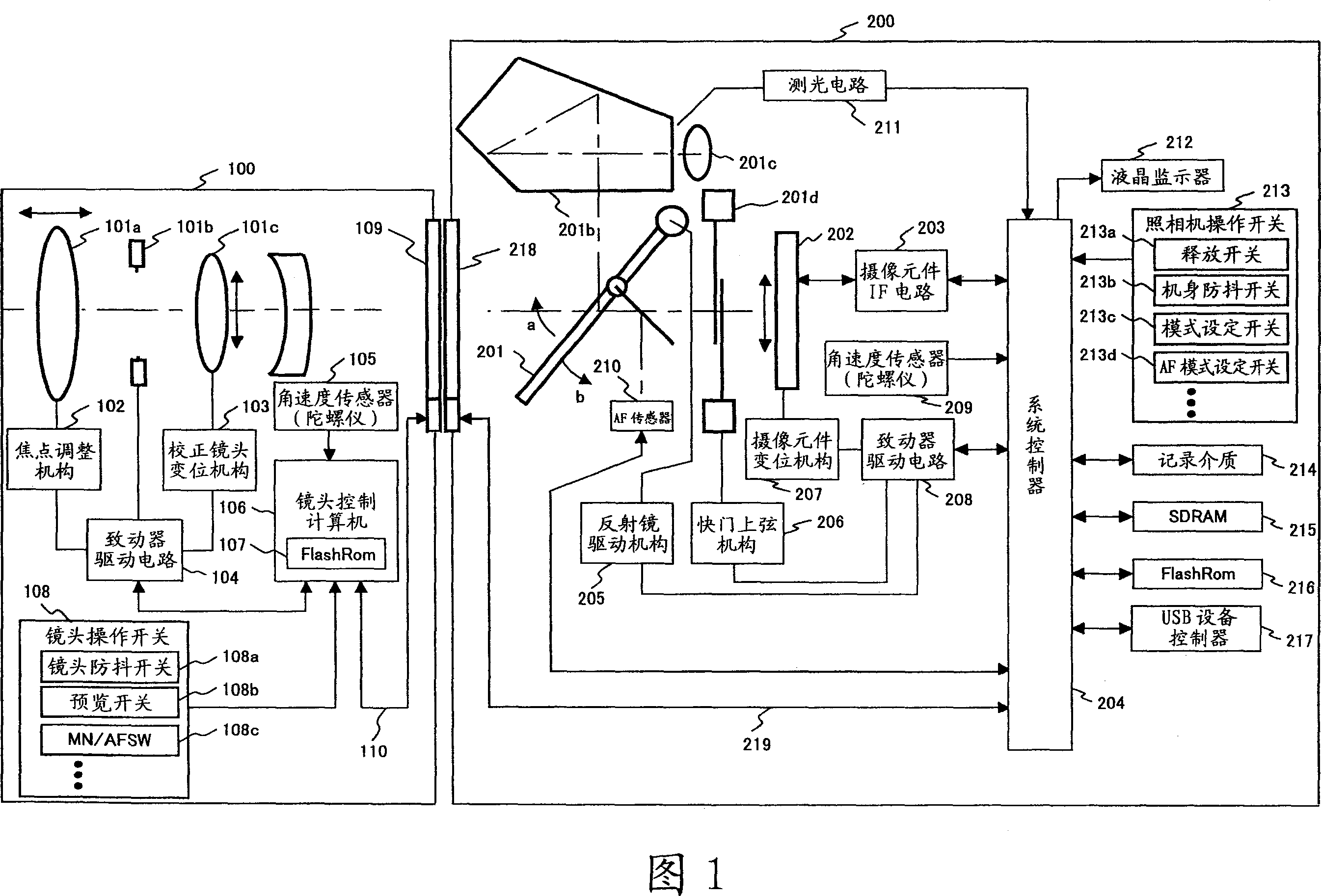
[0038] FIG. 1 is a diagram showing the overall configuration of a camera system of a first embodiment.
[0039] The camera system shown in FIG. 1 is constituted by a photographic lens 100 and a camera body 200 which are detachably connected to each other.
[0040] The photographic lens 100 has an optical system having at least: a focus lens (focus lens) 101a that adjusts focus; a diaphragm 101b that limits the amount of incident light; and a correction lens 101c that changes the optical axis of incident light.
[0041] In addition, the photographic lens 100 has: a focus adjustment mechanism 102 for adjusting the focus by shifting the focus lens 101a along the optical axis; and a correction lens for displacing the correction lens 101c on a plane perpendicular to the optical axis or tilting the correction lens 101c Displacement mechanism 103; Actuator drive circuit 104 for driving aperture 101b, focus adjustment mechanism 102, correction lens displacement mechanism 103; The len...
no. 2 approach
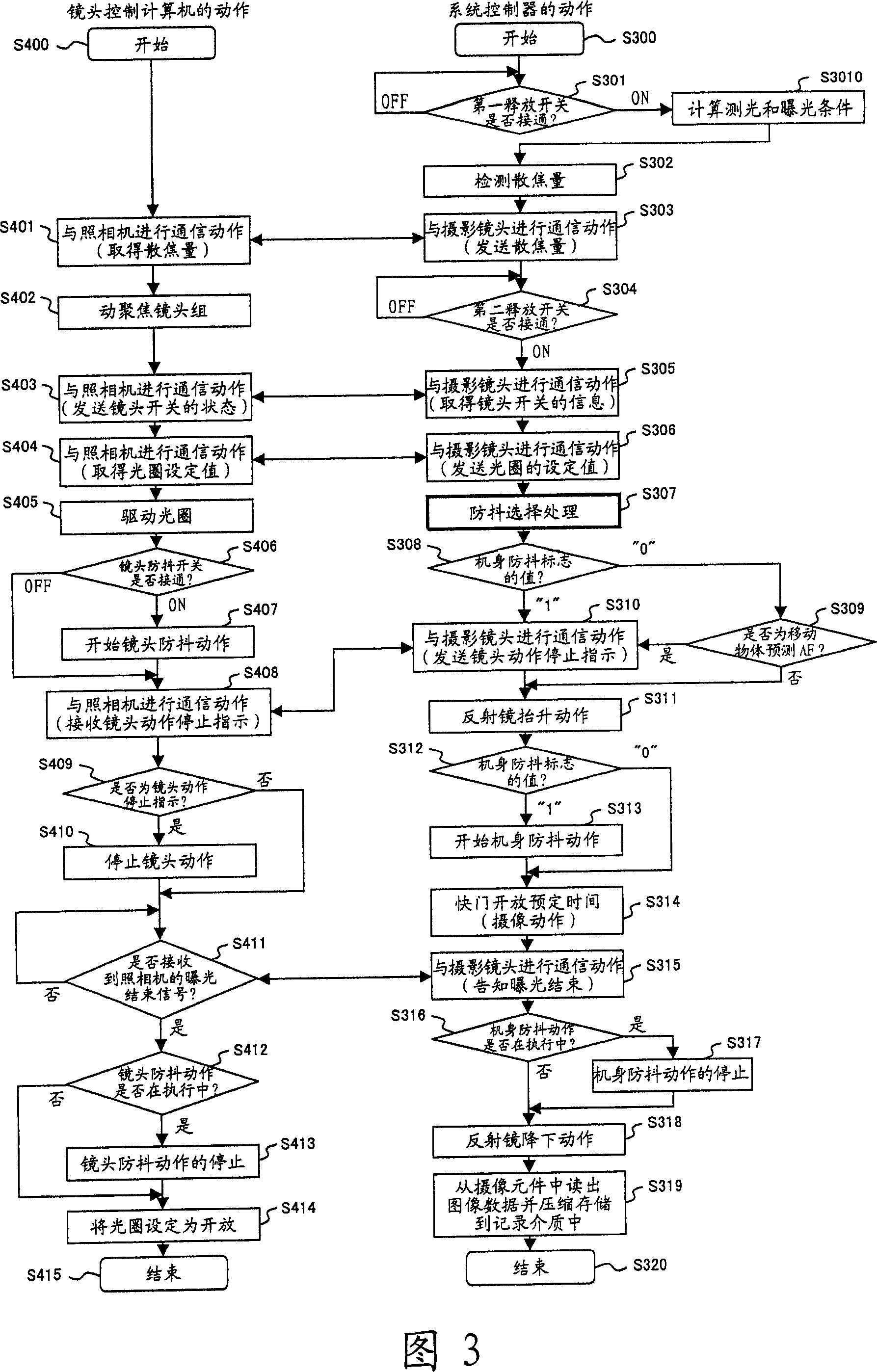
[0192] FIG. 18 is a flowchart showing the shooting operation of the camera system of the second embodiment. Next, the anti-shake operation of the camera system of the second embodiment will be described based on this flowchart.
[0193] When the camera operation switch 213 is operated, for example, an interrupt signal is input to the system controller 204, and the MPU of the system controller 204 executes a program stored at a predetermined address in the FlashRom 216 based on the interrupt signal, and starts a shooting operation, etc. (step S1800 ).
[0194] In addition, the following processing is realized by the respective MPUs of the lens control computer 106 and the system controller 204 shown in FIG. Express as the subject of processing.
[0195] When the photographing operation starts, the system controller 204 checks whether the first release switch is turned on by the release switch 213a. Then, when the first release switch is not in the on state (off state), the p...
no. 3 approach
[0247] FIG. 20 is a diagram showing the overall configuration of a camera system of a third embodiment.
[0248] The camera system shown in FIG. 20 includes a photographic lens 100 and a camera body 500 that are detachably connected to each other.
[0249] The photographic lens 100 is the photographic lens explained in FIG. 1 . In addition, the camera body 500 is a camera body that further includes a display panel 501 that displays various shooting information and a viewfinder display unit 502 that displays shooting information in a viewfinder in addition to the camera body 200 described in FIG. 1 .
[0250] On the display panel 501, in addition to the display related to the anti-shake function of the taking lens 100 and the camera body 500 (hereinafter referred to as "anti-shake display 506"), the light metering mode, AF mode, and image quality mode are also displayed. , shutter speed, aperture value, remaining battery level, number of shots that can be taken, color space se...
PUM
 Abstract
Description
Claims
Application Information
 - R&D
- Intellectual Property
- Life Sciences
- Materials
- Tech Scout
- Unparalleled Data Quality
- Higher Quality Content
- 60% Fewer Hallucinations
Browse by: Latest US Patents, China's latest patents, Technical Efficacy Thesaurus, Application Domain, Technology Topic, Popular Technical Reports.
© 2025 PatSnap. All rights reserved.Legal|Privacy policy|Modern Slavery Act Transparency Statement|Sitemap|About US| Contact US: help@patsnap.com