
A control method and device for permanently magnetic brushless motor

A technology of permanent magnet brushless motor and control method, applied in the direction of single motor speed/torque control, current controller, electronic commutator, etc. The effect of real-time and reliability

Inactive Publication Date: 2007-05-16
SHANGHAI HAOKONG INFORMATION TECH
View PDF1 Cites 25 Cited by
  • Summary
  • Abstract
  • Description
  • Claims
  • Application Information

AI Technical Summary

Problems solved by technology

At present, the development level of electric vehicles at home and abroad is no longer a problem in short-distance driving. The "bo

Method used


Image

  • A control method and device for permanently magnetic brushless motor
  • A control method and device for permanently magnetic brushless motor
  • A control method and device for permanently magnetic brushless motor

Examples


Embodiment Construction

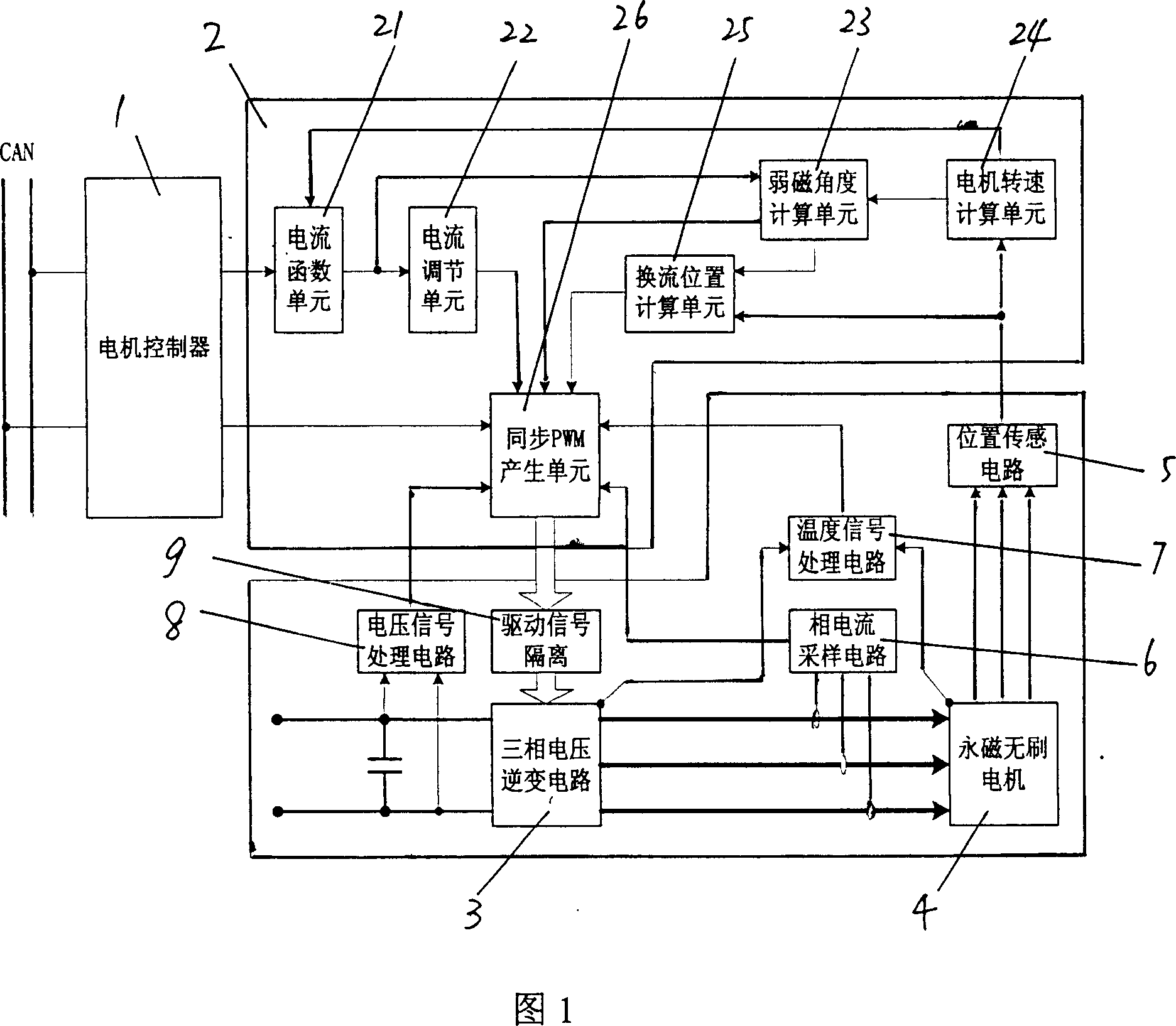
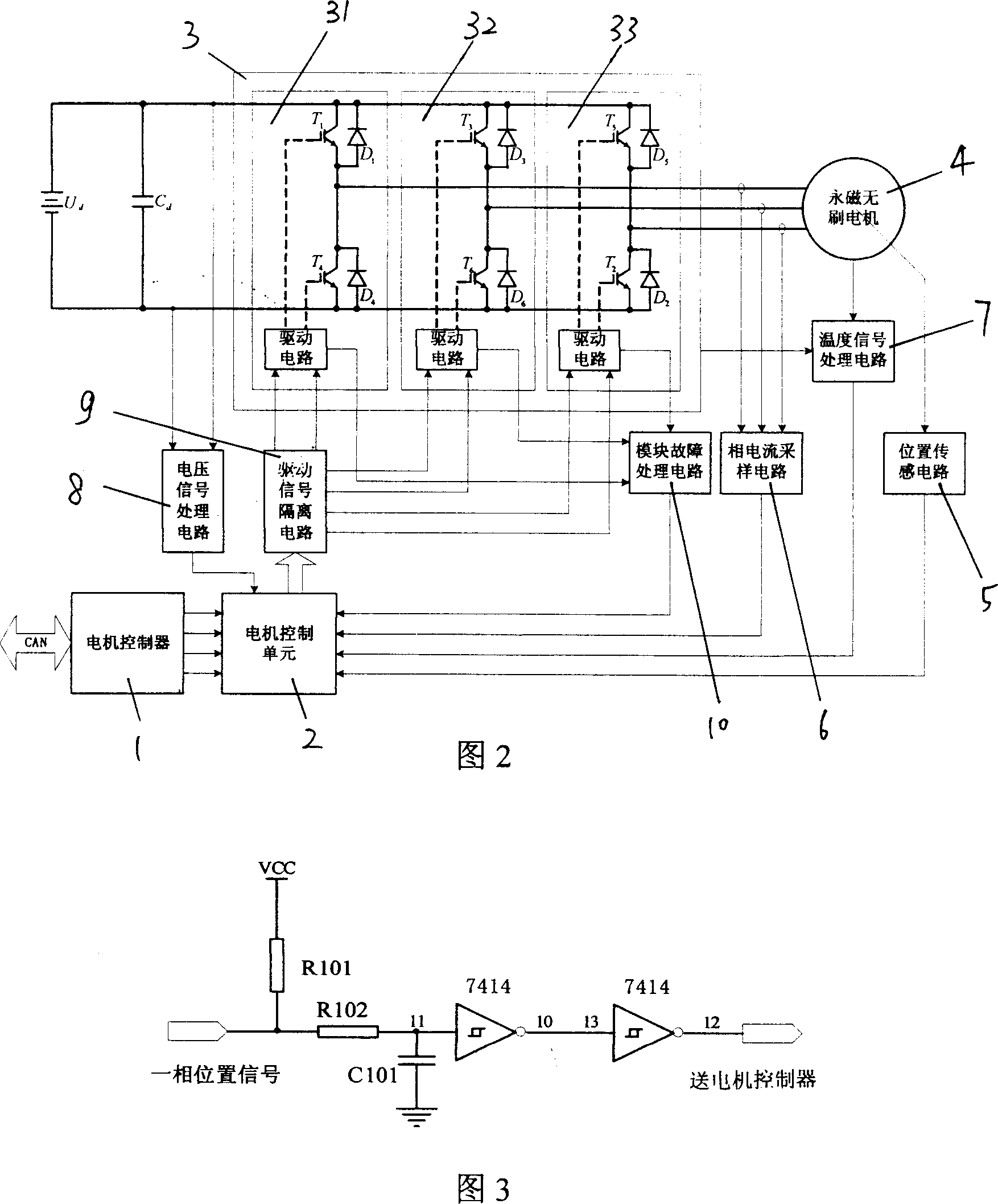
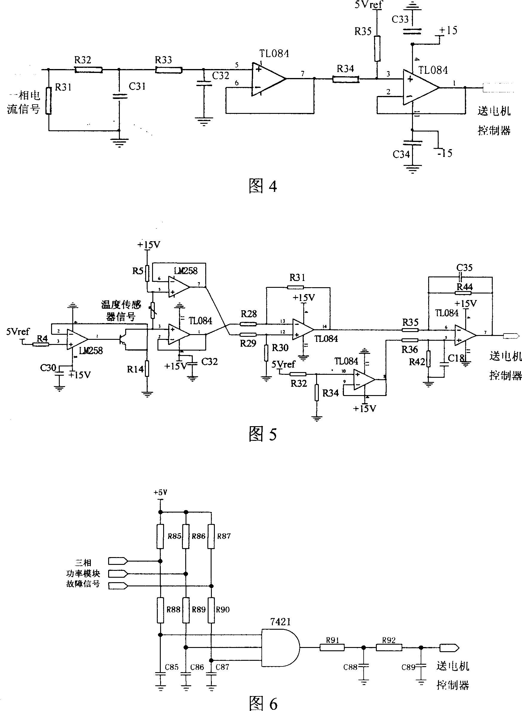
[0025] The present invention will be further described below in conjunction with the accompanying drawings and embodiments.

[0026] In view of the constant power requirements of electric vehicles for motors and their control systems, permanent magnet brushless motors output constant torque when the speed is below the rated speed, and output constant power between the rated speed and the maximum speed. Corresponding to the constant power operation section of the permanent magnet brushless motor, under the premise of a certain DC bus voltage, when the back EMF of the motor is close to the DC bus voltage, if the speed is increased again, the back EMF of the motor will exceed the DC bus voltage. Since the rotor magnetic field of the permanent magnet brushless motor is constant, the air gap magnetic field can only be weakened by the demagnetization of the stator current. By controlling the stator current to advance the air gap flux (opposite potential) by an angle α, the direct axi...


PUM


Abstract

The disclosed control method for permanent-magnet brushless motor comprises: using a current function table to convert torque signal from controller into a given current signal; setting the output duty ratio of the given current and feedback current after passing a current regulator for PWM control; using a synchronous PWM signal generator to determine PWM sequence and action time according to all of the duty ratio and current conversion advance angle and current HALL signal for the weak magnetic control. This invention is high real-time and reliable, and can achieve system requirement on stability and dynamic regulation.

Description

Technical field: [0001] The invention relates to the technical field of electric vehicles, in particular to a permanent magnet brushless motor control method and device suitable for electric vehicles. Background technique: [0002] Cars are one of the most important means of transportation in the world, but the dwindling of oil resources and the pollution of fuel vehicles to the environment have become urgent problems to be solved in automotive applications; the research and development of non-polluting, low-noise electric vehicles has become a global trend Already on the rise, the replacement of fuel vehicles by electric vehicles is the development direction of the automobile industry in the 21st century. [0003] Electric vehicles put forward higher and more complex requirements for their power devices than usual: frequent start / stop, fast speed up / down, high torque output when climbing at low speeds, low torque output during high-speed economical driving, and high energy ...

Claims


Application Information

Patent Timeline
IPC IPC(8): H02P6/08H02P6/16H02P6/17H02P6/28
Inventor 徐国卿张舟云
Owner SHANGHAI HAOKONG INFORMATION TECH
Learn More