Elevator emergency stop device
A stop device, emergency technology, applied in the direction of transportation and packaging, lifts, etc.
- Summary
- Abstract
- Description
- Claims
- Application Information
AI Technical Summary
Problems solved by technology
Method used
Image
Examples
Embodiment approach 1
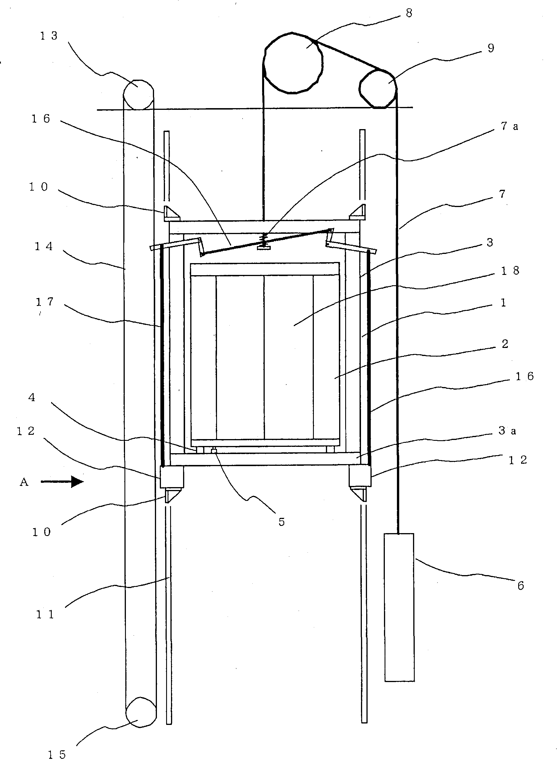
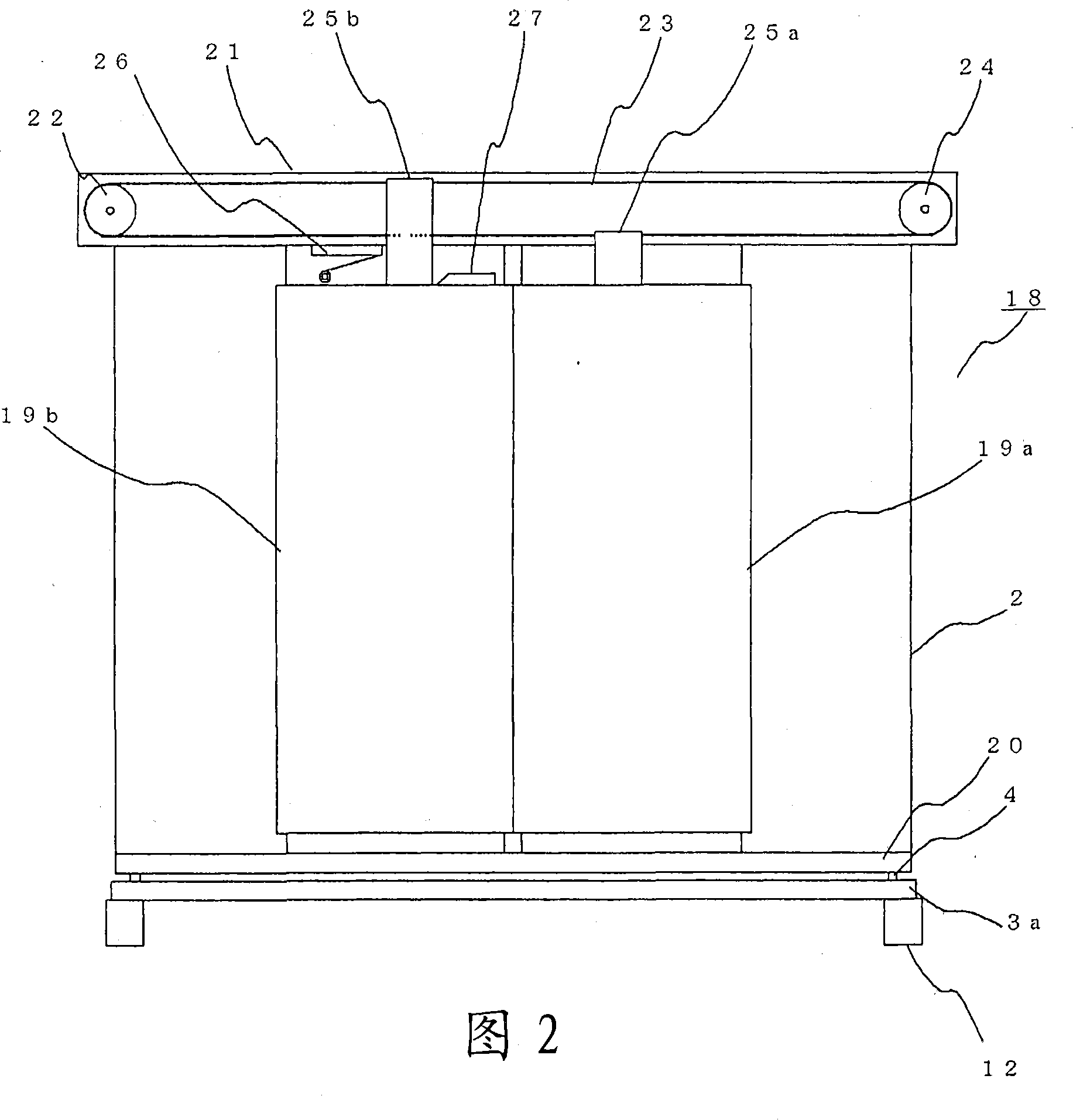
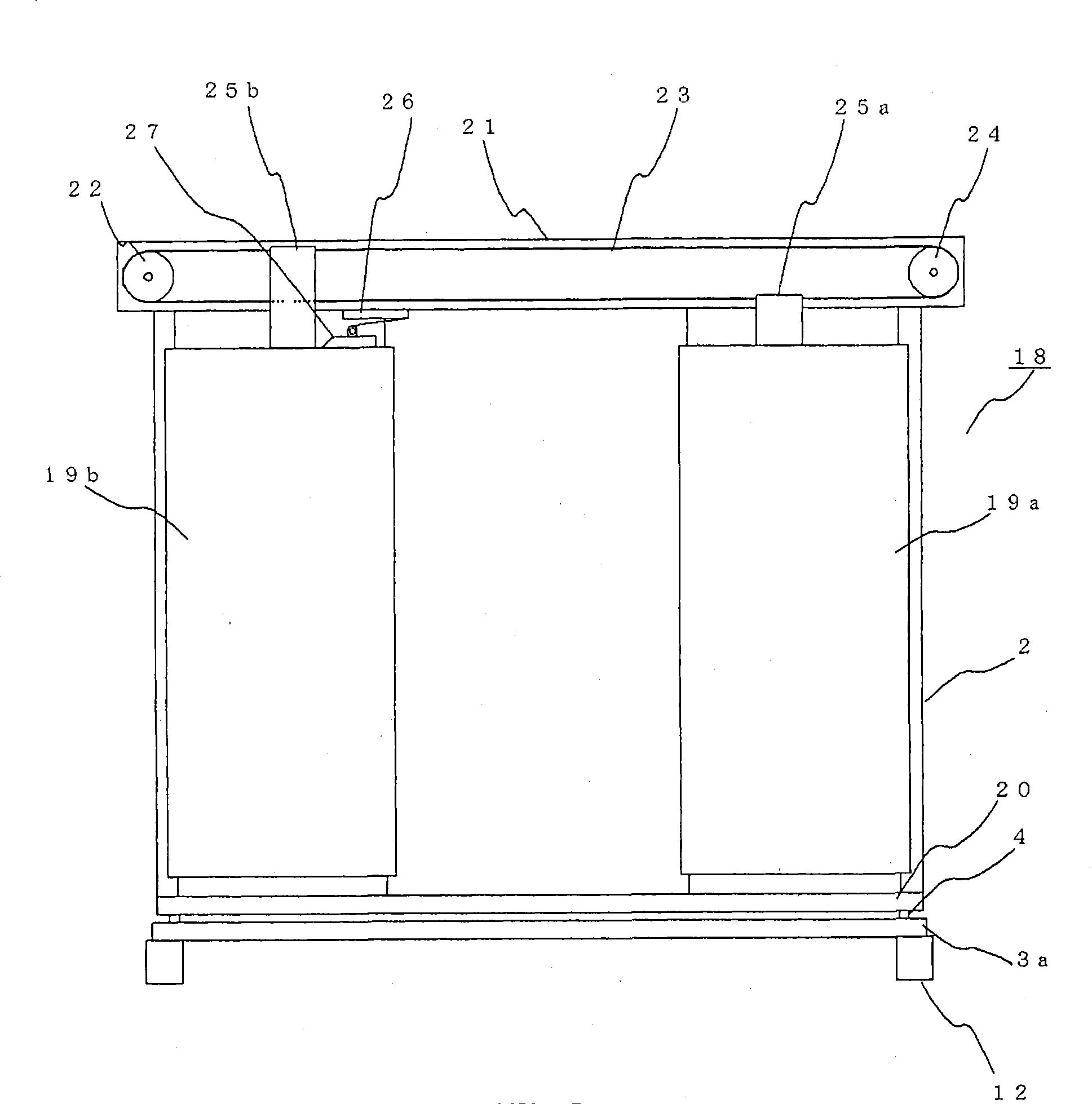
[0041] Figure 1 to Figure 6 It is a figure explaining the elevator emergency stop device in Embodiment 1 for implementing this invention, figure 1 It is a figure which shows the whole structure diagram of an elevator, Fig. 2, image 3 It is a figure showing the main part of the door of the car, Figure 4 is a diagram showing the main parts of the elevator emergency stop device, Figure 5 , Figure 6 It is a diagram explaining the operation of the elevator emergency stop device.
[0042] exist figure 1 Among them, the lifting body 1 includes: a car 2 for carrying passengers; and a frame body 3 for supporting the car 2 . In addition, a car chassis 3a is provided at the bottom of the frame body 3. In order to prevent the vibration from the frame body 3 from being transmitted to the car 2 during lifting, a rubber rubber rubber is installed between the car chassis 3a and the car 2. Elastomer4. In addition, a weighing device 5 for measuring the mass of passengers entering a...
Embodiment approach 2
[0073] Figure 7 It is a figure which shows the elevator emergency stop apparatus in Embodiment 2 for carrying out this invention. Compared with Embodiment 1, in this embodiment, the sprag position adjustment means 56 which consists of the stopper 56a and the drive body 56b using a rack and pinion mechanism is changed. exist Figure 7 Among them, the wedge position adjustment unit 57 of the emergency stop device 12a of this embodiment is provided with a stopper 57a that can slide up and down along the frame member 51 and abuts against the upper end of the wedge 55. and a driver 57b that drives the stopper 57a. The stopper 57a is formed in a rod shape and is threaded. Moreover, in the wedge position adjustment unit 57, there are also provided: a nut 58 screwed on the stopper 57a; a belt 59 wound around the nut 58; and a pulley 60 rotated by the driver 57b. , and the belt 59 is wound around the pulley 60 . In addition, the constituent elements having the same reference nume...
Embodiment approach 3
[0077] Figure 8 , Figure 9 , Figure 10 An elevator emergency stop device in Embodiment 3 for carrying out the present invention is shown. Figure 8 It is a figure which shows the main part of the elevator emergency stop apparatus 12b of this embodiment. exist Figure 8Among them, with respect to Embodiment 1, this embodiment is provided with: a locking body 70, its locking stopper 56a; The numbers in the mark indicate the corresponding part. The locking body 70 is formed in a substantially L-shape, one end is pivotally attached to the rotation shaft 70a, and the other end has a terminal portion 70b formed to mesh with the teeth of the driving body 56b. The drive body 56b is locked by the meshing of the terminal portion 70b with the teeth of the drive body 56b, whereby the stopper 56a is locked. Furthermore, the locking body 70 has a restoring unit that restores the terminal portion 70b in a direction away from the driving body 56b, that is, in the direction of the arr...
PUM
 Abstract
Description
Claims
Application Information
 - R&D
- Intellectual Property
- Life Sciences
- Materials
- Tech Scout
- Unparalleled Data Quality
- Higher Quality Content
- 60% Fewer Hallucinations
Browse by: Latest US Patents, China's latest patents, Technical Efficacy Thesaurus, Application Domain, Technology Topic, Popular Technical Reports.
© 2025 PatSnap. All rights reserved.Legal|Privacy policy|Modern Slavery Act Transparency Statement|Sitemap|About US| Contact US: help@patsnap.com


